Lenovo Storage S3200/S2200 Setup Guide 59
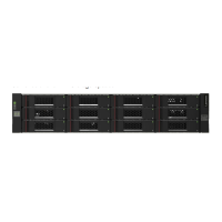
12-drive enclosure front panel LEDs
The enclosure bezel is removed to reveal the underlying 2U12 enclosure front panel LEDs. The front panel
LEDs—including LFF disk LEDs—are described in the table below the illustration.
Figure 36 LEDs: 2U12 enclosure front panel
The enclosure bezel for this model provides the EMI protection for the LFF disk drive modules. The bezel
should be securely attached to the enclosure during operation (see Enclosure bezel attachment on page 56
and Figure 34 on page 57).
CAUTION: Whether configured with or without an air filter, to ensure adequate EMI protection, the
enclosure bezel should be properly installed while the enclosure is in operation.
LED Description Definition
1 Enclosure ID Green — On
Enables you to correlate the enclosure with logical views presented by
management software. Sequential enclosure ID numbering of controller
enclosures begins with the integer 0. The enclosure ID for an attached drive
enclosure is nonzero.
2 Disk drive — Upper LED See Disk drive LEDs on page 60.
3 Disk drive — Lower LED See Disk drive LEDs on page 60.
4 Unit Locator White blink — Enclosure is identified
Off — Normal operation
5 Fault/Service Required Amber — On
Enclosure-level fault condition exists. The event has been acknowledged but
the problem needs attention.
Off — No fault condition exists.
6 CRU OK Green — On
The enclosure is powered on with at least one power supply operating
normally.
Off — Both power supplies are off; the system is powered off.
7 Temperature Fault Green — On
The enclosure temperature is normal.
Amber — On
The enclosure temperature is above threshold.
21
4
3
5
6
7
Left ear
Right ear
0
4
8
1
5
9
2
6
10
3
7
11
7
5
4
6
(Silk screens on bezel)
Integers on disks indicate drive slot numbering sequence.
Notes: Enclosure bezel is removed to show front panel LEDs.

 Loading...