Lenovo Storage S3200/S2200 Setup Guide 21
2Installing the enclosures
Installation checklist
The following table outlines the steps required to install the enclosures, and initially configure and provision
the storage system. To ensure successful installation, perform the tasks in the order presented.
1
See the Lenovo Storage CRU Installation and Replacement Guide for illustrations and narrative describing attachment of enclosure
bezels to 2U24 and 2U12 chassis. See also Enclosure bezel attachment and removal on page 56.
2
For more about hosts, see the “About hosts” topic in the Storage Manager Guide.
3
The Storage Management Console is introduced in Accessing the SMC on page 45. See the Storage Manager Guide or online
help for additional information.
NOTE: Additional installation notes:
• Controller modules within the same enclosure must be of the same type.
• For optimal performance, do not mix 6 Gb and 3 Gb disk drives within the same enclosure.
FDE considerations
The Full Disk Encryption feature available via the management interfaces requires use of self-encrypting
drives (SED) which are also referred to as FDE-capable disk drive modules. When installing FDE-capable
disk drive modules, follow the same procedures for installing disks that do not support FDE. The exception
occurs when you move FDE-capable disk drive modules for one or more disk groups to a different system,
which requires additional steps.
Table 3 Installation checklist
Step Task Where to find procedure
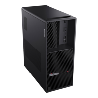
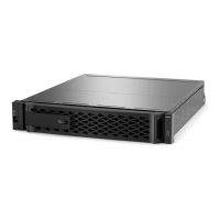
1. Install the controller enclosure and optional
drive enclosures in the rack, and attach the
enclosure bezel.
1
See the rack-mount bracket kit installation instructions
pertaining to your enclosure. Also refer to the bezel
attachment instructions for your enclosure
2. Connect controller enclosure and optional
drive enclosures.
See Connecting the controller enclosure and drive enclosures
on page 22.
3. Connect power cords. See Powering on/powering off on page 28.
4. Test enclosure connectivity. See Testing enclosure connections on page 28.
5. Install required host software. See Host system requirements on page 30.
6. Connect hosts.
2
See Connecting the enclosure to hosts on page 30.
7. Connect remote management hosts.
2
See Connecting a management host on the network,
page 40.
8. Obtain IP values and set network port IP
properties on the controller enclosure.
See Obtaining IP values on page 41.
For USB CLI port and cable use, see Appendix D.
9. Use the CLI to set the host interface protocol. See CNC technology on page 30. The CNC models allow
you to set the host interface protocol for your qualified SFP
option. Use the
set host-port-mode command as
described in the CLI Reference Guide or online help.
10. Perform initial configuration tasks
3
:
• Sign-in to the web-browser interface to
access the application GUI.
• Verify firmware revisions and update if
necessary.
• Initially configure and provision the system
using the Storage Management Console.
Topics below correspond to bullets at left:
See “Getting Started” in the web-posted Lenovo Storage
Manager Guide.
See Updating firmware. Also see the same topic in the
Storage Manager Guide.
See “Configuring the System” and “Provisioning the System”
topics in the Storage Manager Guide or online help.

 Loading...