60 LED descriptions
Disk drive LEDs
You must remove the enclosure bezel to facilitate visual observation of disk LEDs. Alternatively, you can use
management interfaces to monitor disk LED behavior.
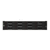
Figure 37 LEDs: Disk drive modules
For information about disk drive types supported in S3200/S2200 LFF and SFF disk drive modules, see
Disk drives used in S3200/S2200 enclosures on page 15.
For information about replacing a disk drive module in an S3200/S2200 controller enclosure or an
E1024/E1012 drive enclosure, see the “Replacing a disk drive module” topic in the CRU Installation and
Replacement Guide.
For information about creating a disk groups, see the “Provisioning the system” topic within the Storage
Manager Guide.
IMPORTANT: For information about self-encrypting disk (SED) drives, see FDE considerations on page 21
and the Storage Management Guide or online help.
NOTE: Additional information pertaining to disk drive LED behavior is provided in the supplementary
tables on the following page.
LED No./Description Color State Definition
1— Power/Activity Green On
Blink
Off
The disk drive module is operating normally.
The disk drive module is initializing; active and processing
I/O; performing a media scan; or the disk group is initializing
or reconstructing.
If not illuminated and Fault is not illuminated, the disk is not
powered on.
2— Fault Amber On
Blink
Off
The disk has failed; experienced a fault; is a leftover; or the
disk group that it is associated with is down or critical.
Physically identifies the disk; or locates a leftover (also see Blue).
If not illuminated and Power/Activity is not illuminated, the disk
is not powered on.
Blue Blink Leftover disk from disk group is located (alternates blinking
amber).
21
2.5" SFF disk drive module
2
1
3.5" LFF disk drive module
(see table below)
(see table below)

 Loading...