Lenovo Storage S3200/S2200 Setup Guide 17
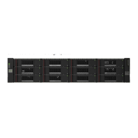
S3200 SAS controller module — rear panel components
Figure 6 shows host interface ports configured with 12 Gbit/s HD mini-SAS (SFF-8644) connectors.
Figure 6 S3200 SAS controller module face plate (HD mini-SAS)
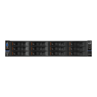
S2200 CNC controller module — rear panel components
Figure 7 shows CNC ports configured with SFPs supporting either 4/8/16 Gb FC or 10GbE iSCSI. The
SFPs look identical. Refer to the CNC LEDs that apply to the specific configuration of your CNC ports.
Figure 7 S2200 CNC controller module face plate (FC or 10GbE iSCSI)
1 HD mini-SAS ports used for host connection
2 CLI port (USB - Type B) [see Appendix D]
3 Service port 2 (used by service personnel only)
4 Reserved for future use
5 Network port
6 Service port 1 (used by service personnel only)
7 Disabled button (used by engineering only)
(Sticker shown covering the opening)
8 mini-SAS expansion port
CACHE
CLI
CLI
LINK
ACT
6Gb/s
SERVICE−1SERVICE−2
ACT
LINK
12Gb/s
S
S
A
ACT
LINK
SAS 0 SAS 1
ACT
LINK
12Gb/s
S
S
A
ACT
LINK
SAS 2 SAS 3
1 CNC ports used for host connection
(see Install an SFP transceiver on page 80)
2 CLI port (USB - Type B) [see Appendix D]
3 Service port 2 (used by service personnel only)
4 Reserved for future use
5 Network port
6 Service port 1 (used by service personnel only)
7 Disabled button (used by engineering only)
(Sticker shown covering the opening)
8 mini-SAS expansion port
CACHE
CLI
CLI
LINK
ACT
6Gb/s
SERVICE−1SERVICE−2
PORT 0 PORT 1
5
2 3 6 8
1
7
4
= FC LEDs
= 10GbE iSCSI LEDs

 Loading...