21Backplanepowerconnector1
22Backplanepowerconnector2
Usedtoconnectthepowercable(s)fromthebackplane.
24262830Systemfanconnectors
Therearefourhot-swapsystemfansandtwodummysystemfansinstalledinthesystemfancageinyour
server.Eachsystemfanconnectorisusedtoconnectacorrespondinghot-swapsystemfan.
23Microprocessorsocket2
27Microprocessorsocket1
Iftheserverhastwomicroprocessors,eachofthemicroprocessorissecuredinthemicroprocessorsocket
onthesystemboardandaheatsinkisinstalledabovethemicroprocessortoprovidecooling.Iftheserver
hasonlyonemicroprocessor,themicroprocessorsocket2isprotectedbyamicroprocessorsocketcover.
2529Memoryslots
Thereare12memoryslotsonthesystemboard.Fordetailedinformation,see“Memorymoduleinstallation
rules”onpage95.
Systemboardjumpersandswitches
Thistopicprovidesinformationaboutthejumpersandswitchesonthesystemboard.
Note:Dependingonthemodel,yourservermightlookslightlydifferentfromtheillustrationsinthistopic.
Ajumperisashortlengthofconductorusedtosetuporadjustaprintedcircuitboard,suchasthesystem
boardofacomputer.Ajumperusuallyisencasedinanon-conductiveblockofplasticforconvenientuse
andtoavoidanypossibledamagetoalivecircuit.Jumperpinsarrangedingroupsonthesystemboardare
calledjumperblocks.Whentwoormorejumperpinsarecappedwithajumper,anelectricalconnectionis
madebetweenthemandtheequipmentisthusinstructedtoactivatecertainsettingsaccordingly.
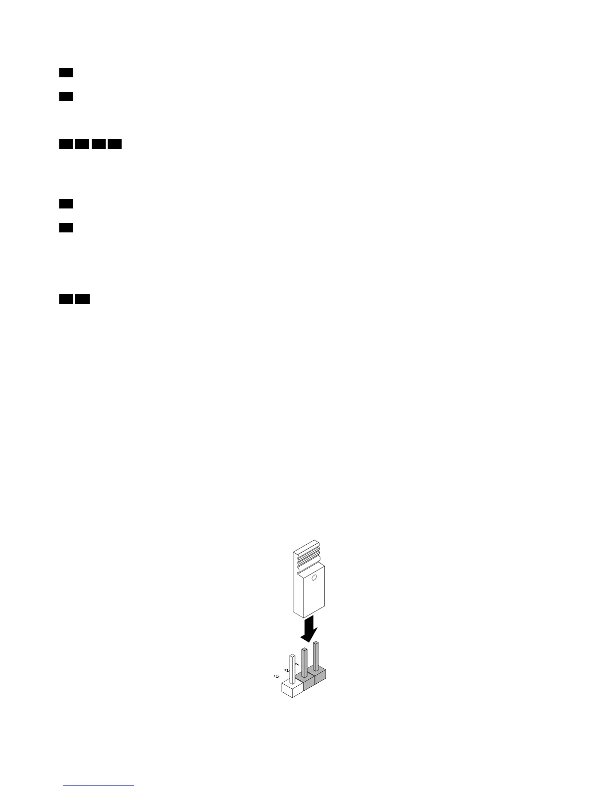
Thefollowingillustrationshowsajumperinthedefaultsettingposition(pin1andpin2).Thisisthecorrect
positionfornormaloperation.
Figure38.Defaultjumpersetting
50ThinkServerRD430UserGuide