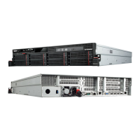
5.Locatethefailingpowersupplyinyourserver.Removethefivescrews1to5thatsecurethepower
supplyassembly.
Figure53.Removingthescrewsthatsecurethepowersupplyassembly
6.Liftthefailingpowersupplyassemblyupandoutofyourserver.
7.Touchthestatic-protectivepackagethatcontainsthenewpowersupplyassemblytoanyunpainted
surfaceontheoutsideoftheserver.Then,removethenewpowersupplyassemblyfromthepackage.
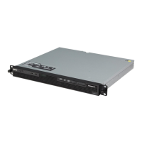
8.Notetheorientationofthenewpowersupplyassemblyandthenpositionitintothechassis.Ensurethat
thefivescrewholesinthenewpowersupplyassemblyarealignedwiththecorrespondingholesinthe
chassis.Then,installthefivescrewstosecurethenewpowersupplyassembly.
Figure54.Installingthescrewstosecurethepowersupplyassembly
9.Connectthepowercablestothesystemboard.See“Systemboardcomponents”onpage32.
10.Reinstalltheservercover.See“Reinstallingtheservercoverandreconnectingcables”onpage106.
11.Connectthepowercordtothepowercordconnectoronthenewpowersupplyassembly.
12.Ifyouareinstructedtoreturntheoldpowersupplyassembly,followallpackaginginstructionsanduse
anypackagingmaterialsthataresuppliedtoyouforshipping.
Removingandreinstallingtheslim-optical-drivebracket
Attention:Donotopenyourserverorattemptanyrepairbeforereadingandunderstanding“Safetyinformation”
onpageiiiand“Guidelines”onpage53.
Beforeyoubegin,printalltherelatedinstructionsorensurethatyoucanviewthePDFversiononanother
computerforreference.
82ThinkServerRS140UserGuideandHardwareMaintenanceManual
 Loading...