Configuration
7-25
48XX/49XXSHB0399
LECOM code for FDO
The states of the FDOs can be displayed in binary format in C151 or they can be
read out in HEX format via the LECOM interface.
Order of FDOs in C151
Bit 15 Bit 0
0 0 0 Relay FDO12 FDO11 FDO10 FDO9 FDO8 FDO7 FDO6 FDO5 FDO4 FDO3 FDO2 FDO1
4900Str037
1
2
3
4
5
6
7
8
9
10
11
12
13
14
15
16
17
18
19
20
0
01
02
03
04
05
06
07
08
09
10
11
12
13
Bit0
Bit1
Bit2
Bit3
Bit4
Bit5
Bit6
Bit7
Bit8
Bit9
Bit10
Bit11
Bit12
A01
A02
A03
A04
A05
C 116/C 128
N o function
nact <= nx (C 017)
C ontroller enable
n-ctrl. output = M m ax
R eady for operation (R D Y)
P u ls e in h ib it (IM P )
Fault m essage TR IP
Warning
M essage
R FG : input=output
nact = nset
nact = 0
Ia c t = 0
n a c t & Ia c t = 0
C om parator 1
C om parator 2
C 046 or. C 049 > nx
|Ia rm a tu re | > Ix
Ifie ld > Ix
|n a c t| > n x
Brake control
Delay
Delay
Delay
Delay
Relay
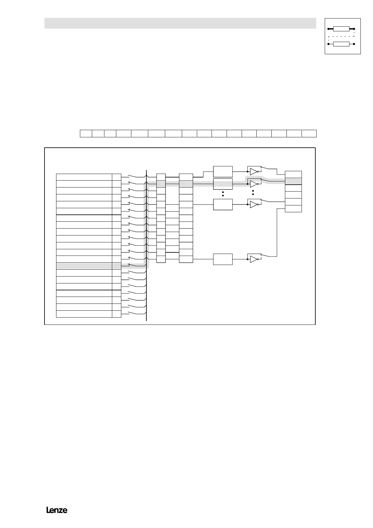
S ig n a l s e le c tio n
C 116/C 117
Input
selection
FDO
C116
Process
data channel
LEC O M 1 / LE C O M 2
C151
FDO level
C 116/C 118
Term inal
signals
Exam ple:
Function nact & lact = 0 assigned to FD O 02
C 116 = 2, C 117 = 13
FIG 7-10 Overview of the freely assignable digital outputs (FDO)