Configuration
7-43
48XX/49XXSHB0399
4900Str042
X7 X5
X8X1 X9
SW I
R
X7 X5
X8X9
R
X7 X5
X8X9
R
j
, n -c trl.
Encoder
output
Resolver
Increm ental
encoder
M aster drive w ith
m aster integrator
Factor
j , n -c trl.
Encoder
output
Resolver
Increm ental
encoder
Slave 1
Factor
j , n -c trl.
Encoder
output
Resolver
Increm ental
encoder
Slave 2
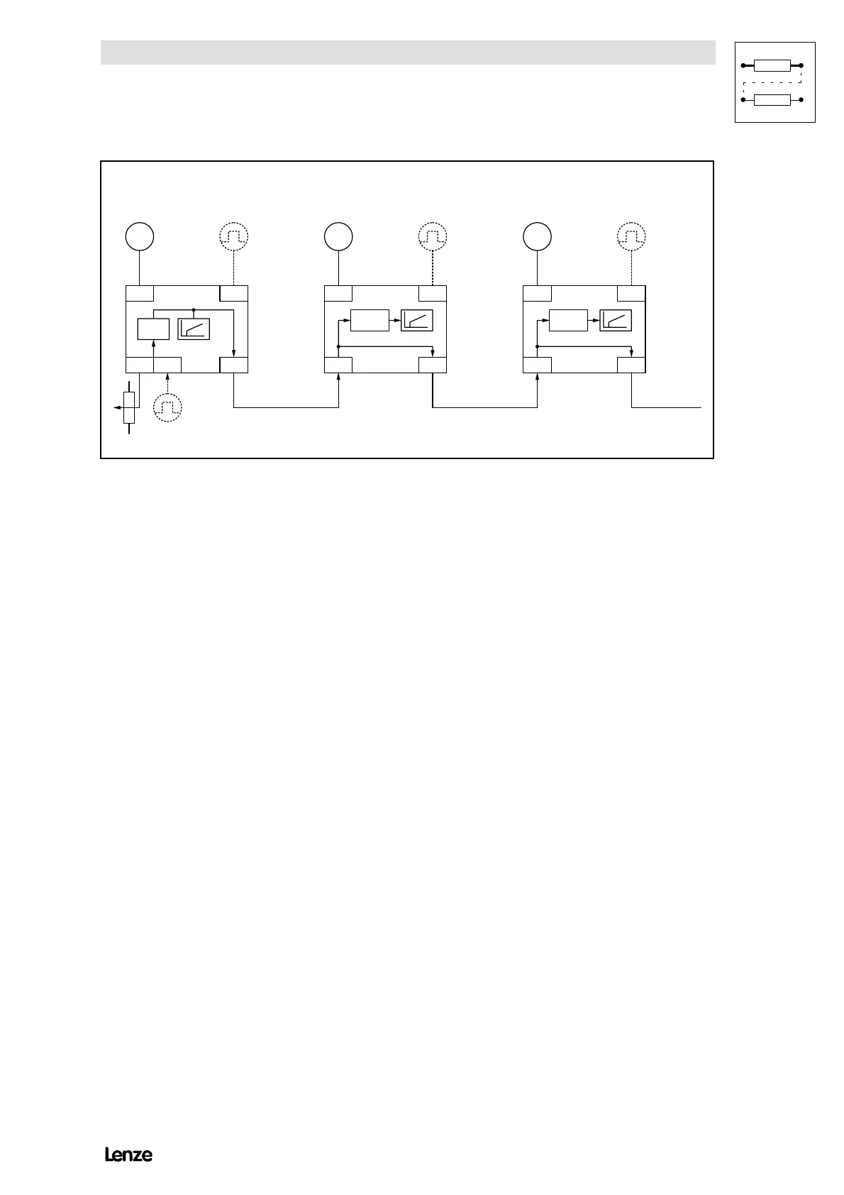
FIG 7-15 Connection diagram for the configuration of the digital frequency bar
M Master drive with master integrator
S1 Slave 1
S2 Slave 2
RResolver
Features
( Either resolver or incremental encoder feedback
( Hardware connection between DF output and DF input
( Another evaluation of the set-value with a factor (numerator/denominator)
for the corresponding slave (gearbox adaptation). Adjustable via LECOM,
motor potentiometer or analog terminal
( External torque limitation possible
( QSP function for the individual drive. The DF set-value will be output
independently of QSP.
( RFR function for the individual drive. The set-value will be output to the DF
output independtly of the QSP.
( Influence possible via codes for phase trimming and speed correction (via
LECOM, motor potentiometer, analog terminal or one of the signal sources
under C145)
( Following error limit adjustabel via code
( TRIP when reaching the phase controller limit
( Speed limit = 1.8 ¼ C011
( Phase controller influence of 0 (0 = deactivated) adjustable up to 1.00
( No alternative set-value conditioning available
(JOG, additional set-value, set-value integrator...)