Electrical installation
Wiring of the feedback system
Encoder connection
5
128
EDKCSEX064 DE/EN/FR 6.0
SinCos encoders and SinCos absolute value encoders with Hiperface
Features
Input/output frequency: 0 ... 200 kHz
Internal resistance (R
i
): 221 W
Offset voltage for signals SIN, COS, Z: 2.5 V
ƒ The differential voltage between signal track and reference track must
not exceed 1 V ± 10 %.
ƒ The connection is open−circuit monitored (fault message "Sd8")
ƒ For encoders with tracks sine, sine and cosine, cosine:
– Assign RefSIN with sine.
– Assign RefCOS with cosine.
ƒ For SinCos absolute value encoders with Hiperface, the serial interface (RS
485) is available instead of the zero track (Z track).
SIN
COS
0.5 V
0.5V
RefSIN
RefCOS
2.5 V
2.5 V
0V
0V
X8
5
1
9
6
SIN
V
CC
GND
Z
R1 (+KTY)
R2 (-KTY)
1
2
3
4
5
6
7
8
9
COS
<50m
RefCOS
RefSIN
Z
KTY
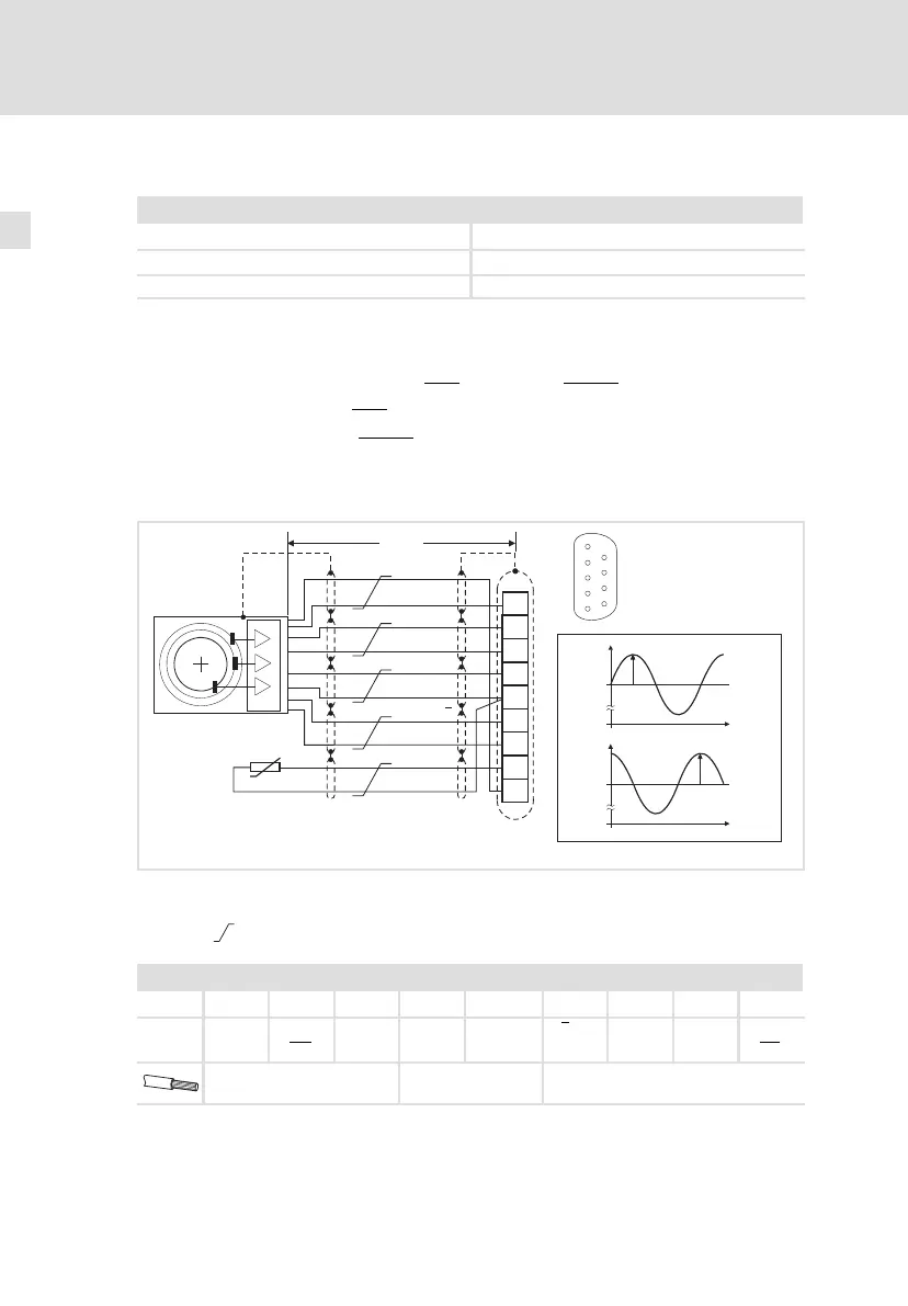
ECSXA023
Fig. 5−14 Connection of SinCos encoder
Signals in case of clockwise rotation
Cores twisted in pairs
Assignment of plug connector X8: Sub−D 9−pole
Pin 1 2 3 4 5 6 7 8 9
Signal SIN RefCOS
(cos
)
COS V
CC
GND
(R2/−KTY)
Z or
−RS458
Z or
+RS485
R1
(+KTY)
RefSIN
(sin
)
0.14 mm
2
(AWG 26)
1 mm
2
(AWG 18)
0.14 mm
2
(AWG 26)
 Loading...


