Elektrische Installation
Rückführsystem verdrahten
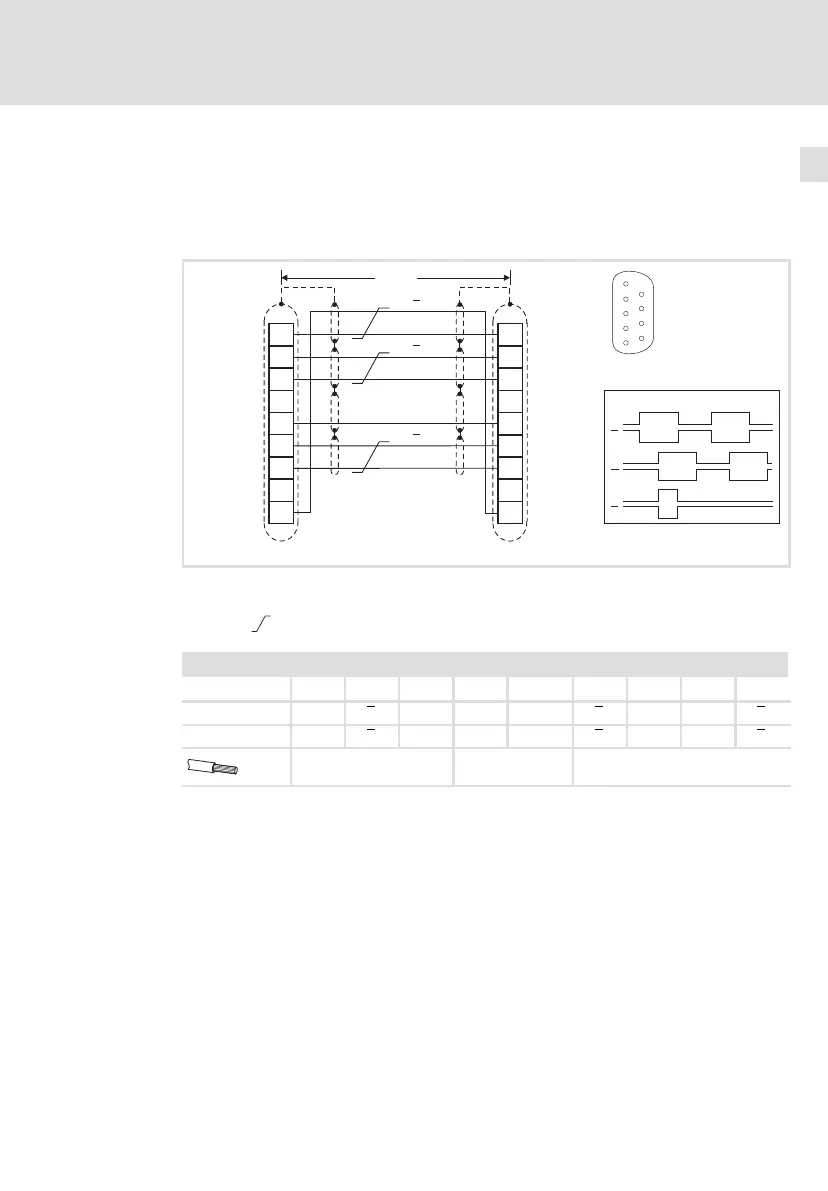
Leitfrequenzeingang/−ausgang (Encoder−Nachbildung)
5
65
EDKCSEX064 DE/EN/FR 6.0
Verdrahtung
ƒ 1 Slave am Master:
Master und Slave direkt über Schnittstelle X8 miteinander verdrahten.
B
GND
Z
1
2
3
4
5
6
7
8
9
1
2
3
4
5
6
7
8
9
A
<50m
A
B
Z
A
A
B
Z
B
Z
X8
(ECS-Slave)
X8
(ECS-Master)
5
1
9
6
ECSXA029
Abb. 5−15 Anschluss des Leitfrequenzeingangs/−ausgangs X8 (Master « Slave)
Signale bei Rechtslauf
Paarweise verdrillte Adern
Belegung der Stiftleiste X8: Sub−D 9−polig
Pin 1 2 3 4 5 6 7 8 9
Eingangssignal B A A ˘ GND Z Z ˘ B
Ausgangssignal B A A ˘ GND Z Z ˘ B
0,14 mm
2
(AWG 26)
1 mm
2
(AWG 18)
0,14 mm
2
(AWG 26)
 Loading...


