EasyManua.ls Logo

Lenze ECS series User Manual

Lenze ECS series
483 pages
To Next Page IconTo Next Page
To Previous Page IconTo Previous Page
Page #24 background imageLoading...
Page #24 background image
Preface and general information
System block introduction
Access via absolute addresses
1
24
EDBCSXA064 EN 3.2
1.5.4 Access via absolute addresses
You can also access the inputs and outputs of the system blocks via absolute addresses
according to standard IEC 61131−3:
For inputs: For outputs:
%IXa.b.c %QXa.b.c
a = node number
b = word address
c = bit address
In this Manual, the absolute addresses can be retrieved in the system variable table of the
corresponding system block.
Example: Table with the inputs of the SB Inputs_Digital of the ECSxA... axis module
Variable Data
type
Signal
type
Address Display
code
Display
format
Notes
DIGIN_bCInh_b
BOOL binary
%IX1.0.0 ˘ ˘
Controller inhibit ˘ takes
direct effect on the
device control DCTRL.
DIGIN_bIn1_b %IX1.0.1
C0443 bin
DIGIN_bIn2_b %IX1.0.2
DIGIN_bIn3_b %IX1.0.3
DIGIN_bIn4_b %IX1.0.4
DIGIN_b_safe_standstill_b %IX1.0.5
"Safe torque off"
(former "safe standstill")
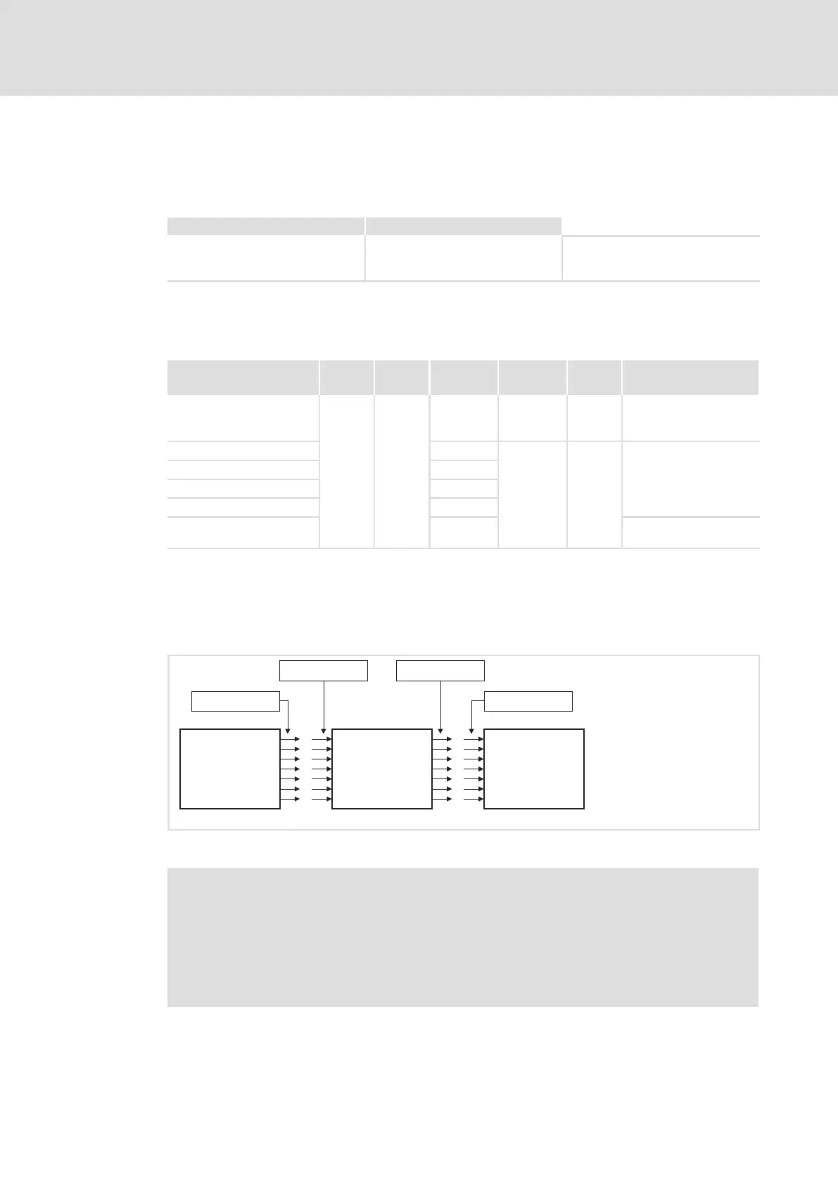
1.5.5 Definition of the inputs/outputs
For connecting the application program with the hardware, system blocks are connected
with program organisation units (POU):
SB
SB-Output
POE-Input POE-Output
SB-Input
SBPOE
Fig. 1−1 Plan: Connecting system blocks to a program organisation unit (POU)
Note!
Inputs and outputs are always classified from the program’s point of view.
ƒ Logical SB inputs are always hardware−side outputs of the ECSxA axis...
module
ƒ Logical SB outputs are always hardware−side inputs of the ECSxA axis...
module

Table of Contents

Other manuals for Lenze ECS series

Questions and Answers:

Lenze ECS series Specifications

General IconGeneral
CategoryControl Unit
Protection classIP20
Product seriesECS series
Output currentDepends on specific model
Communication interfacesCANopen, Ethernet
Relative humidity5% to 95% (non-condensing)

Summary

Preface and General Information

About these Operating Instructions

Provides essential information for connecting and commissioning ECSxA axis modules, including safety instructions.

Features of the ECSxA Axis Module

Lists key features of the ECSxA axis module, including safety functions, CAN interfaces, and feedback systems.

System Block Introduction

Introduces the concept of system blocks (SB) as hardware function blocks integrated into the axis module.

Safety Instructions

General Safety and Application Notes

Covers essential safety measures for personal safety and preventing damage to material assets.

Technical Data

Rated Data

Presents technical specifications including output power, DC-bus voltage, and current ratings for axis modules.

Current Characteristics

Explains how continuous current depends on output voltage and control factor.

Mechanical Installation

Mounting with Fixing Rails (Standard Installation)

Details dimensions and mounting steps for standard installation using fixing rails.

Mounting with Thermal Separation (Push-Through Technique)

Explains mounting requirements for push-through design, including cooling and protection class.

Mounting in Cold-Plate Design

Covers requirements for collective coolers and mounting steps for cold-plate design.

Electrical Installation

Installation According to EMC

Covers electromagnetic compatibility aspects like assembly, filtering, shielding, and earthing.

Power Terminals

Details plug connectors, their assignments, and cable cross-sections for power connections.

Control Terminals

Explains connections for control electronics, digital/analog signals, and safety functions.

Commissioning

Before You Start

Lists prerequisites and checks before initial switch-on, including wiring verification.

Carrying Out Basic Settings with GDC

Details basic settings configuration using the Global Drive Control program, including motor data and feedback.

Setting of the Feedback System

Explains configuration for resolvers, TTL encoders, SinCos encoders, and absolute value encoders.

System Bus (CAN / CAN-AUX) Configuration

Setting the CAN Node Address and Baud Rate

Details setting node addresses and baud rates via DIP switches or codes for CAN interfaces.

Monitoring Functions

Fault Responses

Details the consequences and display options for TRIP, Message, Warning, FAIL-QSP, and Off responses.

Overview of Monitoring Functions

Provides a comprehensive overview of all monitoring functions, their sources, and possible responses.

Configuring Monitoring Functions

Covers setting monitoring times for process data input objects, communication errors, and bus states.

Diagnostics

Diagnostics with Global Drive Control (GDC)

Locating diagnostic codes and fault history values within the GDC parameter menu.

Troubleshooting and Fault Elimination

Fault Analysis

Methods for analyzing faults using LED displays, keypads, history buffer, and LECOM status words.

Malfunction of the Drive

Lists common drive malfunctions, their causes, and suggested remedies.

Fault Messages

Provides an overview of fault messages, their sources, and possible responses.

System Modules

DCTRL_DriveControl (Node Number 121)

Controls axis module states like Quick stop, Operation inhibit, Controller inhibit, and TRIP.

MCTRL_MotorControl (Node Number 131)

Controls driving machine functions including phase, speed, and motor control.

Appendix

Code Table

Comprehensive list of Lenze codes, their settings, and important information.

Related product manuals