System modules
CAN2_IO (node number 32)
Inputs_CAN2
13
292
EDBCSXA064 EN 3.2
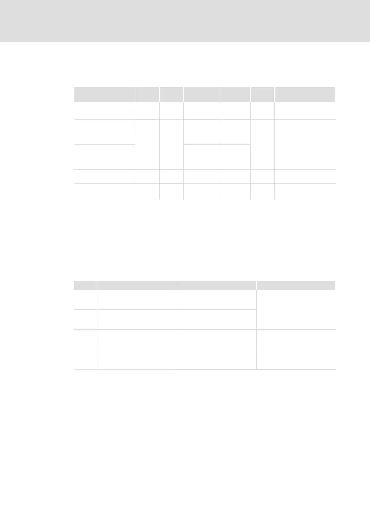
13.9.1 Inputs_CAN2
System variables
Variable Data
type
Signal
type
Address Display
code
Display
format
Comments
CAN2_nInW1_a
integer
analog
%IW32.0 C0866/4
dec [%]
CAN2_nInW2_a %IW32.1 C0866/5
CAN2_bInB0_b
BOOL binary
%IX32.0.0
hex
... ... C0863/3
CAN2_bInB15_b %IX32.0.0
CAN2_bInB16_b %IX32.1.0
... ... C0863/4
CAN2_bInB31_b %IX32.1.15
CAN2_dnInD1_p double
integer
position %ID32.0 C0867/2 dec [inc]
CAN2_nInW3_a
integer analog
%IW32.2 C0866/6
dec [%]
CAN2_nInW4_a %IW32.3 C0866/7
User data
The first 4 bytes from the 8 bytes of received user data are assigned to several variables of
different data types. According to requirements, they thus can be evaluated by the PLC
program as:
ƒ binary information (1 bit)
ƒ quasi−analog value (16 bit)
ƒ angle information (32 bit)
Byte Variable (1 bit) Variable (16 bit) Variable (32 bit)
1, 2 CAN2_bInB0_b
...
CAN2_bInB15_b
CAN2_nInW1_a
CAN2_dnInD1_p
3, 4 CAN2_bInB16_b
...
CAN2_bInB31_b
CAN2_nInW2_a
5, 6
CAN2_nInW3_a
7, 8
CAN2_nInW4_a

 Loading...


