System modules
DFIN_IO_DigitalFrequency (node number 21)
Inputs_DFIN
13
336
EDBCSXA064 EN 3.2
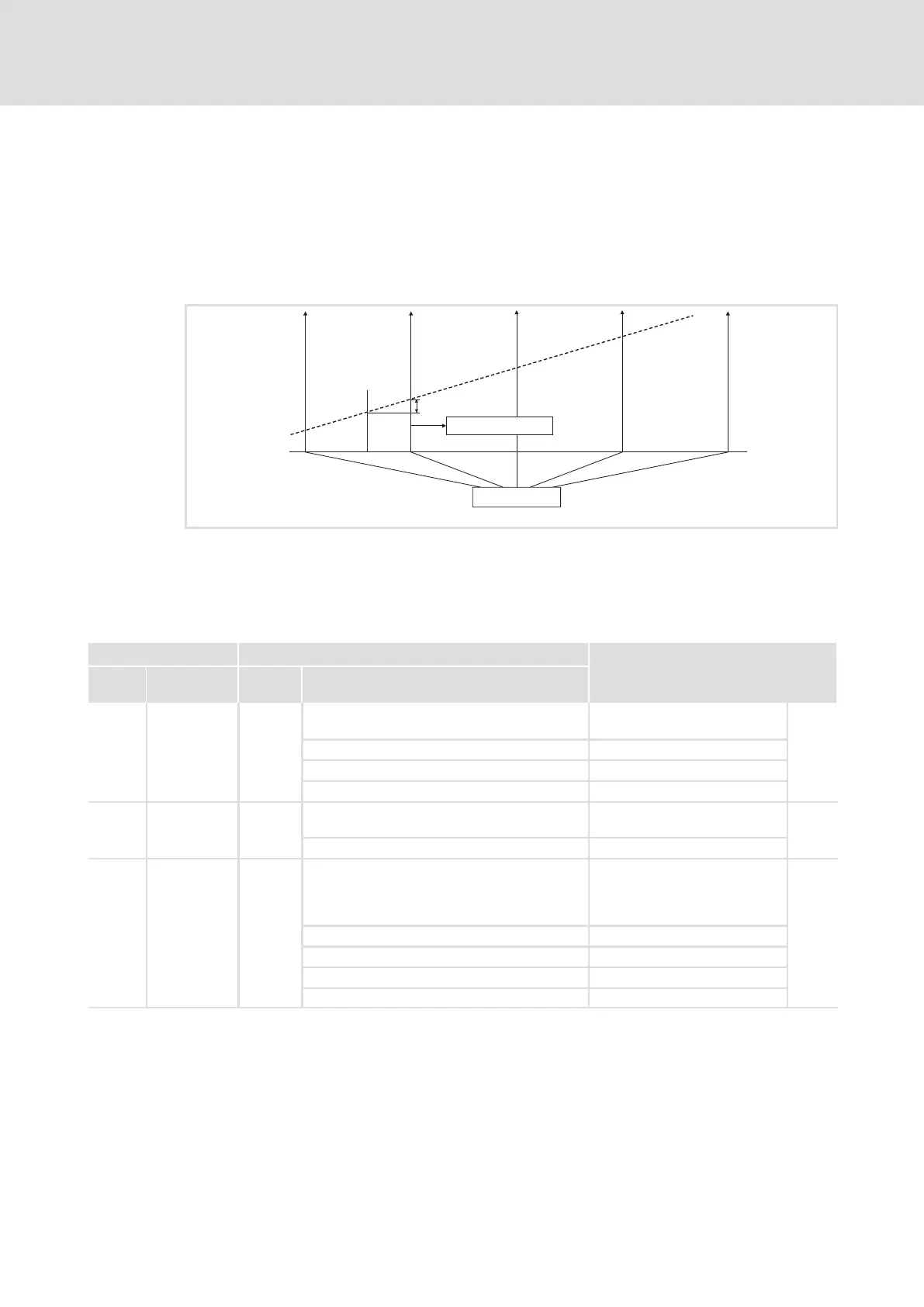
13.16.1.2 Configurating touch probe
Process
If an edge change on the input actuating a TP (e. g. X6/DI1) occurs, the instantaneous
phase value (master frequency input value) is stored in the operating system by means of
a very fast interrupt.
DFIN_dnIncLastScan_p
TP
j
Fig. 13−24 Function diagram of a Touch Probe (TP)
Time−equidistant start of an interval task
J Phase−angle signal
Codes
Code Possible settings IMPORTANT
No. Designation Lenze/
{Appl.}
Selection
C0428 DFIN TP sel. 0
DFIN touch probe signal source
336
331
0 Zero pulse of position encoder (C0490) X7/X8
1 Touch probe input TP1 X6/DI1
2 Zero pulse of digital frequency input X8
C0429 TP1 delay 0
DFIN dead time compensation
TP1 (DI1)
336
331
−32767 {1 inc} 32767
C0431 DFIN TP Edge 0
DFIN touch probe TP1 edge
(for touch probe via digital input
X6/DI1 (C0428 = 1))
336
0 Rising edge TP1
1 Falling edge TP1
2 Rising and falling edge TP1
3 Switched off

 Loading...


