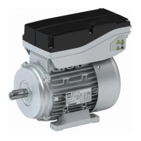
Connecon via ICN connector
Posion of the connecons
Posion Meaning Note
1 ICN-M23 connector, 6-pole
•
Power connecon
•
Brake connecon
•
PE connecon
-
In addion to ICN-M23 connector , 8-pole:
•
Motor temperature monitoring connecon TKO or PT1000
If feedback is present, the PT1000 temperature sensor is wired in
the feedback connector.
2 ICN-M23 connector
•
Feedback connecon
•
PT1000 temperature sensor connecon
-
3 ICN-M17 connector
•
Blower connecon
If required, the terminal box can be rotated step by step by 90 °
aer loosening the screws in the terminal box.
Power and brake connecon
ICN-M23 connector assignment
6-pin
Contact Name Meaning
1 BD1 DC +/AC holding brake
2 BD2 DC -/AC holding brake
PE PE PE conductor
4 V Power phase U
5 V Power phase V
6 W Power phase W
ICN-M23 connector assignment
8-pin
Contact Name Meaning Figure
1 V Power phase U
PE PE PE conductor
3 W Power phase W
4 V Power phase V
A TB1 / TP1 / R1 Temperature monitoring: TCO
B TB2 / TP2 / R2 Temperature monitoring: TCO
C BD1 / BA1 DC +/AC brake ≤ 230 V
D BD2 / BA2 DC -/AC brake ≤ 230 V
Electrical installaon
Motor connecon
Connecon via ICN connector
42
 Loading...