Installation
4-26
L
MA9300PLC EN 1.4
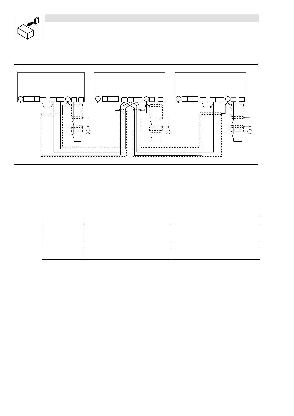
System bus connection (X4)
9300PLC123
UV
W
932X - 933X
PE
UV
W
932X - 933X
PE
28 A4
PE
28
A4
K1
Ctrl.
enable
PE
PE
PE
PE
UV
W
932X - 933X
PE
28 A4
PE
K1
Ctrl.
enable
K1
Ctrl.
enable
GND
HI LO
GND
HI LO
RA2
GND
HI LO
RA1
Fig. 4-13 Wiring of the system bus
RA1, RA2 Bus termination resistors 120 Ω (included in the accessory kit)
• Connection via pluggable screw terminals (double terminals can be used).
• Only connect terminals of the same designation.
• Features of the system cable:
Total cable length up to 300 m 300 m to 1000 m
Cable type LIYCY2x2x0.5mm
2
twisted-pair with shielding
Pair 1: CAN-LOW (LO) and CAN-HIGH (HI)
Pair 2: 2*GND
CYPIMF2x2x0.5mm
2
twisted-pair with shielding
Pair 1: CAN-LOW (LO) and CAN-HIGH (HI)
Pair 2: 2*GND
Cable resistance ≤ 40 Ω/km ≤ 40 Ω/km
Capacitance per unit
length
≤ 130 nF/km ≤ 60 nF/km
• Connection of the bus terminating resistors:
– One resistor 120
Ω at every first and last bus participant.
– On the 93XX controller the resistor can be screwed directly under the terminals X4/HI and
X4/LO.
Features:
• CAN-based with bus protocol according to CANopen (CAL-based Communication Profile
DS301)
• Bus expansion:
– 25 m for max. 1 Mbit/s baud rate
– up to 1 km with reduced baud rate
• Extremely reliable data transmission (Hamming distance = 6)
• Signal level to ISO 11898
• Up to 63 bus devices are possible
• Master functions integrated into the controller
– Data exchange possible between controllers without the participation of a master system
(exchange of digital signals, current ratio control, speed synchronization, etc.)
 Loading...


