Installation
Electrical connection
Group drive
4
EN
40
Lenze ¯ MDKSEMA ¯ 5.0
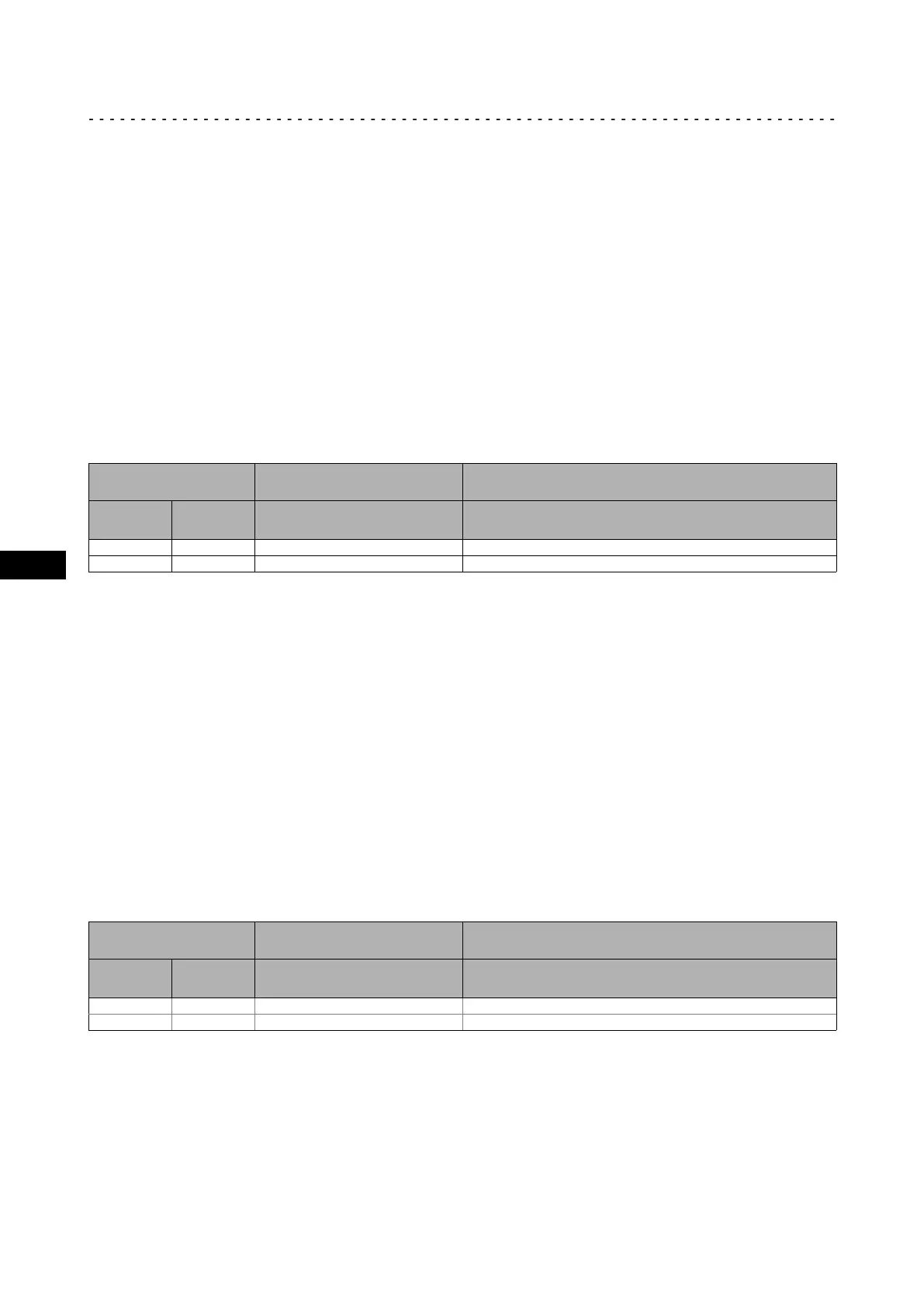
Fuses and cable cross−sections
The instructions relating to fuses and cable cross−sections are applicable under the
following conditions:
¯ Comply with national and regional regulations
Installation in accordance with EN 60204−1
¯ Use of fuses of utilisation category gG/gL or semiconductor fuses of utilisation
class gRL or the indicated automatic circuit breakers.
¯ Use PVC−insulated copper cables
– Conductor temperature < 70 °C, ambient temperature < 40 °C
¯ No bundling of cables or cores, three cores under load.
¯ Typical utilisation 80 %
Fuses Cable cross−sections Max. total of rated mains currents ( 32)
F1 ... F3
L1, L2, L3, PE I
N1
+ I
N2
+ I
N3
+ I
N4
... + I
Nn
Laying system B2 at 40 °C
[A] [A]
[mm
2
] [A]
10 C10 1.5 7.6
16 C16 2.5 (with pin−end connector) 12.2
Fuse
Automatic circuit breaker
Installation in accordance with UL 61800−5−1
¯ Use UL−approved cables:
– Conductor temperature < 75 °C, ambient temperature < 40 °C
¯ Typical utilisation 80 %
¯ Operation from mains 5 kA rms SCCR:
– Use current−limiting UL−approved fuses (UL 248) or automatic circuit breakers
(UL 489), voltage ³ 480 V.
¯ Operation from mains 200 kA rms SCCR:
– Use current−limiting UL−approved fuses (UL 248), current limiting rating from
200 kA rms to max. 5 kA rms, e.g. 15 A class CC.
– It must be ensured that the Lenze Smart Motor is not installed in a control
cabinet.
Fuses Cable cross−sections Max. total of rated mains currents ( 32)
F1 ... F3
L1, L2, L3, PE I
N1
+ I
N2
+ I
N3
+ I
N4
... + I
Nn
at 40 °C
[A] [A]
[AWG] [A]
10 10 16 8.0
15 15 14 (with pin−end connector) 12.0
Fuse
Automatic circuit breaker
 Loading...