Device description
Leuze electronic MLC 520 10
Device synchronization
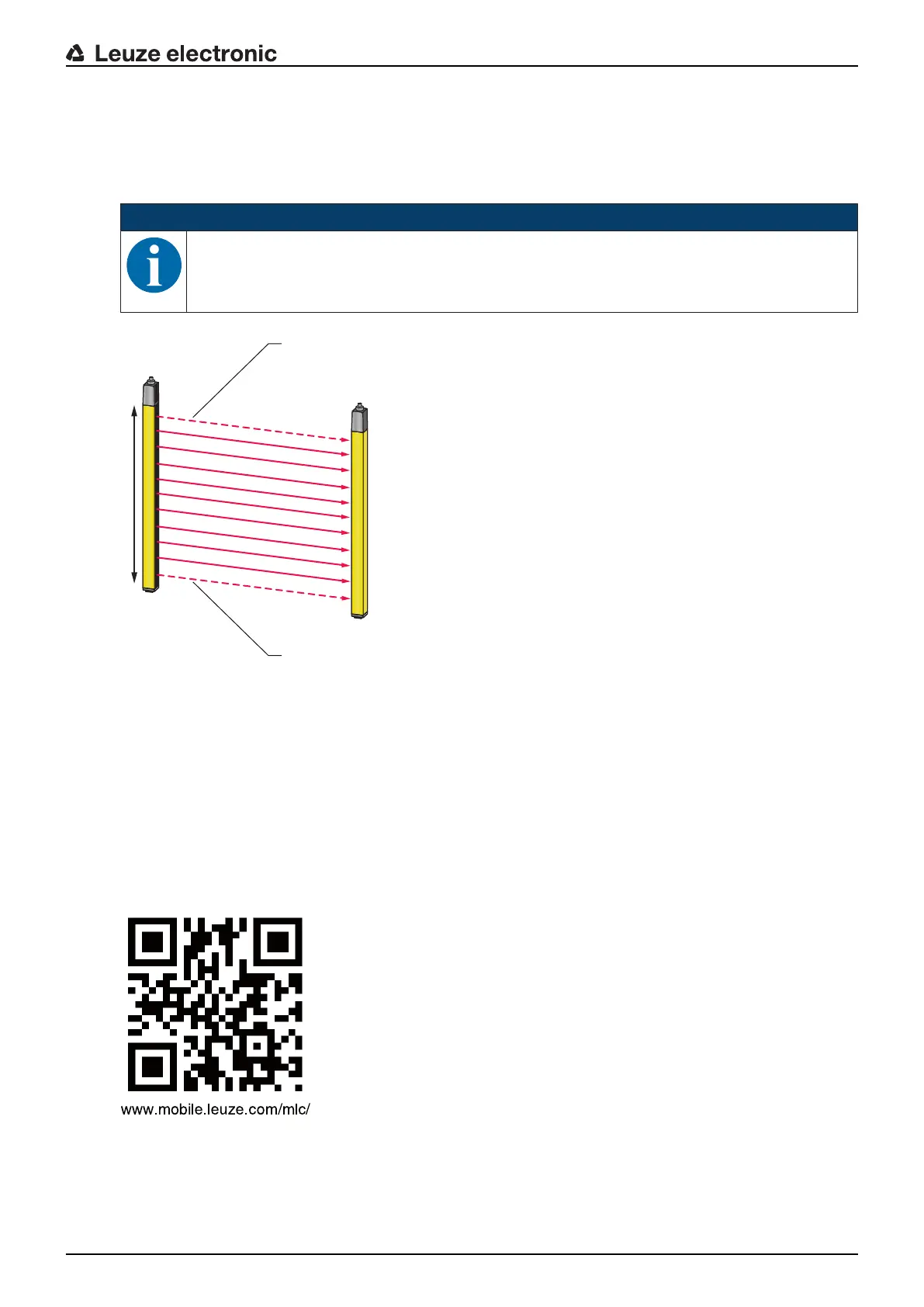
The synchronization of receiver and transmitter for creating a functioning protective field is done optically,
i.e. without cables, via two specially coded synchronization beams. A cycle (i.e. a pass from the first to the
last beam) is called a scan. The length of a scan determines the length of the response time and affects the
calculation of the safety distance (see chapter 6.1.1 "Calculation of safety distanceS").
NOTICE
For the correct synchronization and function of the safety sensor, at least one of the two syn-
chronization beams must be free during synchronization and operation.
a Optically active area, housed in yellow
b Synchronization beams
Fig.3.1: Transmitter-receiver system
QR code
A QR code as well as the corresponding web address are located on the safety sensor.
At the web address, you will find device information and error messages (see chapter 11.3 "Error mes-
sages 7-segment display") after scanning the QR code with a mobile end device or after entering the web
address.
When using mobile end devices, mobile service charges can accrue.
Fig.3.2: QR code with corresponding web address (URL) on the safety sensor
3.2 Connection technology
The transmitter and receiver feature an M12 connector as an interface to the machine control with the fol-
lowing number of pins:

 Loading...


