Device description
Leuze electronic MLC 520 11
Device model Device type Device plug
MLC500 Transmitter 5-pin
MLC520 Standard receiver 8-pin
3.3 Display elements
The display elements of the safety sensors simplify start-up and fault analysis.
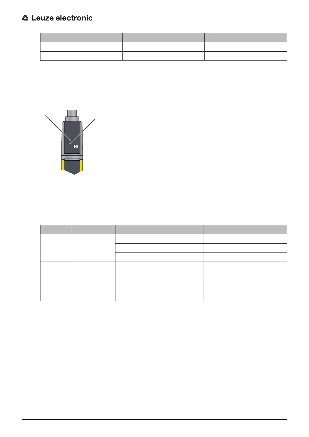
3.3.1 Operating indicators on the MLC500 transmitter
Located in the connection cap on the transmitter are two LEDs which serve as function indicators:
1 LED1, green/red
2 LED2, green
Fig.3.3: Indicators on the MLC500 transmitter
Tab.3.2: Meaning of the LEDs on the transmitter
LED Color State Description
1 Green/red OFF Device switched off
Red Device error
Green Normal operation
2 Green Flashing For 10s after switch-on: reduced
range selected by the wiring of
pin4
OFF Transmission channel C1
ON Transmission channel C2
3.3.2 Operating indicators on the MLC520 receiver
Two LEDs and a 7-segment display for showing the operating state are located on the receiver:

 Loading...


