Device description
Leuze electronic MLC 520 12
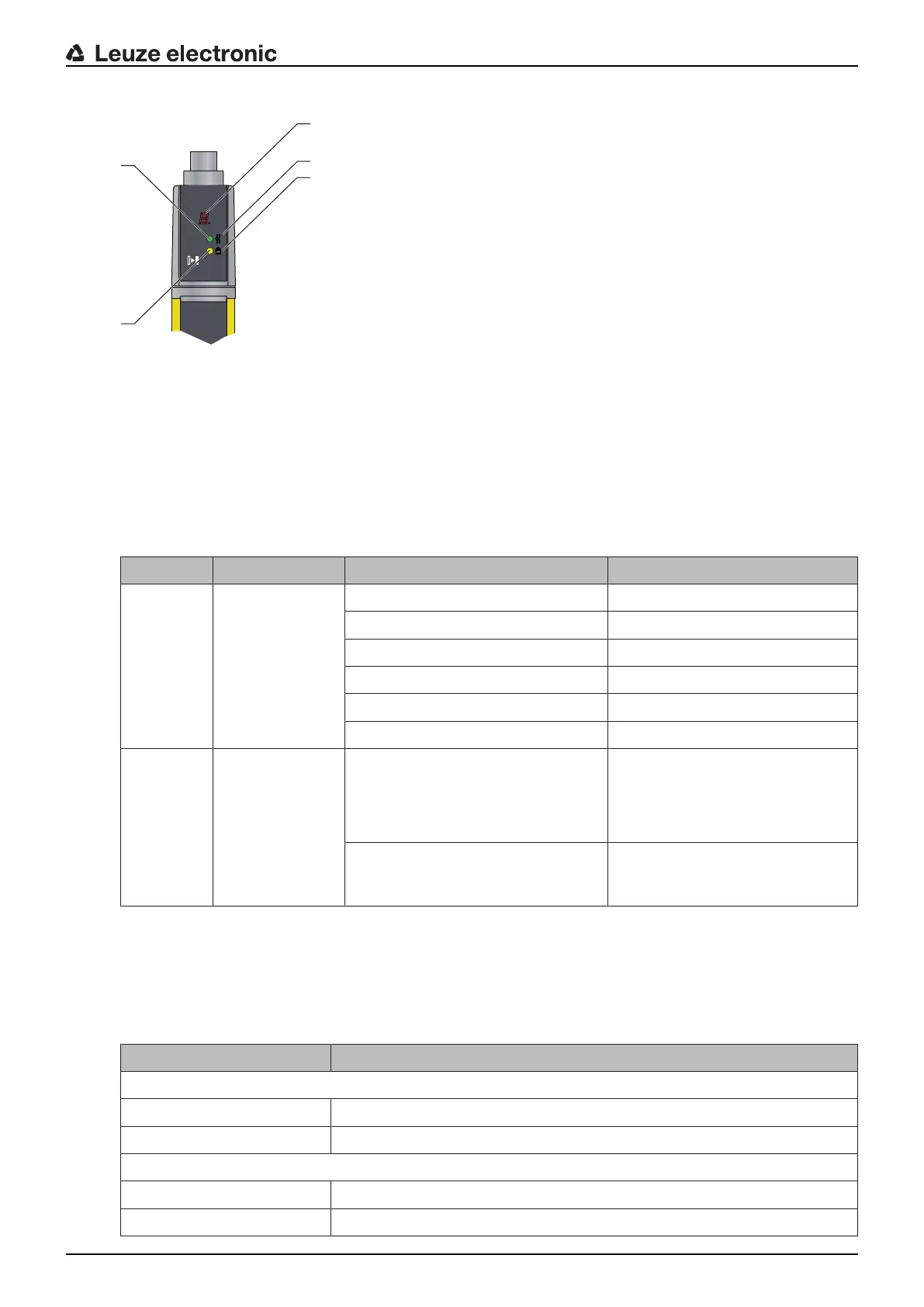
1 LED1, red/green
2 LED2, yellow
3 OSSD icon
4 RES icon
5 7‑segment display
Fig.3.4: Indicators on the MLC520 receiver
Tab.3.3: Meaning of the LEDs on the receiver
LED Color State Description
1 Red/green OFF Device switched off
Red OSSD off
red slowly flashing (approx.1Hz) External fault
red flashing fast (approx.10Hz) Internal fault
Green slowly flashing (approx.1Hz) OSSD on, weak signal
Green OSSD on
2 Yellow OFF • RES deactivated
• or RES activated and enabled
• or RES blocked and protective
field interrupted
ON RES activated and blocked but
ready to be unlocked - protective
field free
7-segment display at the MLC520 receiver
In normal operation, the 7-segment display shows the number of the selected transmission channel. In ad-
dition, it helps during the detailed error diagnostics (see chapter 11 "Troubleshooting") and serves as an
alignment aid (see chapter 8.2 "Aligning the sensor").
Tab.3.4: Meaning of the 7-segment display
Display Description
After switching on
8 Self test
tnn Response time (t) of the receiver in milliseconds (nn)
In normal operation
C1 Transmission channel C1
C2 Transmission channel C2

 Loading...


