Installation
Leuze electronic GmbH + Co. KG BPS 37 21
Table 6.1: Connection description BPS 37
6.3.2 Connecting the SSI interface
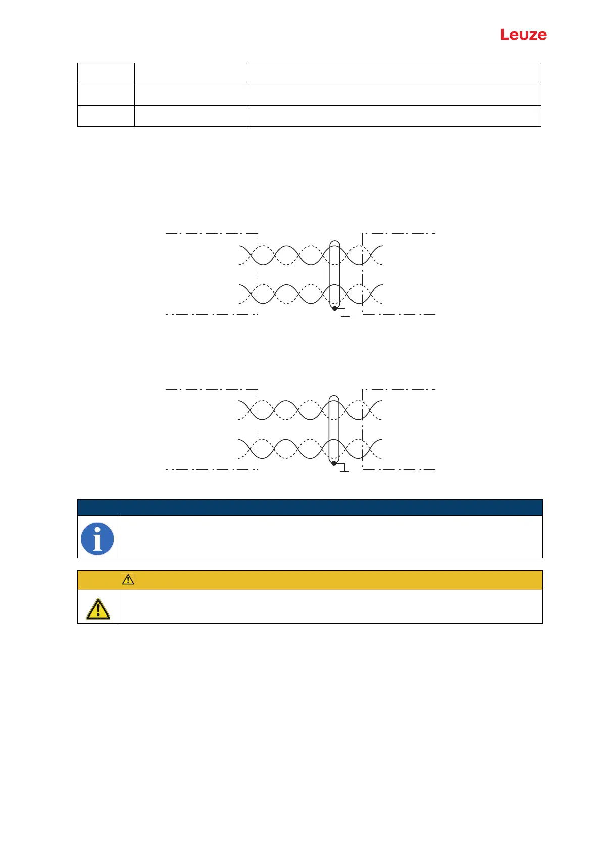
Connection with MA
Figure 6.5: Connection with MA
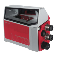
Connection directly with BPS
Figure 6.6: Connection directly with BPS
Connecting the protective conductor PE
BPS 37 without cable: connect PE to the housing of the BPS 37 or to the housing
of the 15-pin SUB-D connector!
BPS 37 with cable KB 031-3000: connect PE to the wire with bl/wh color coding or connect it
to the shield!
BPS with cable and MA 4.7 (MA 4D.7): connect PE to PIN 21 or PIN 22!
6.3.3 Connecting the switching input and switching output
The BPS 37 is provided with a switching input and a switching output. The connection of the switching
input and output is made in accordance with Figure 6.7:
Pin 13 Reserve
Pin 14 Reserve
Pin 15 GND Supply voltage: 0VDC
NOTE
Ensure adequate shielding. Connections 1 and 2 must be twisted in pairs and the entire
interconnection cable must be shielded, and earthed on one side.
ATTENTION!
It is absolutely necessary to connect the protective conductor, since all electrical interference
(EMC couplings) is discharged via the protective conductor connection.
SSI DATA +
SSI DATA -
SSI Clock +
SSI Clock -
SSI DATA +
SSI DATA -
SSI Clock +
SSI Clock -
1/2
3/4
13
7
MA 4.7/MA 4D.7 Control/drive
SSI interface
Terminals
Connection 1
Connection 2
SSI DATA +
SSI DATA -
SSI Clock +
SSI Clock -
SSI DATA +
SSI DATA -
SSI Clock +
SSI Clock -
3
4
6
9
BPS 37 SM 100 Control/drive
SSI interface
Pin
Connection 1
Connection 2