Installation
Leuze electronic GmbH + Co. KG BPS 37 20
6.3 Connection
6.3.1 Connecting the BPS 37 (SSI)
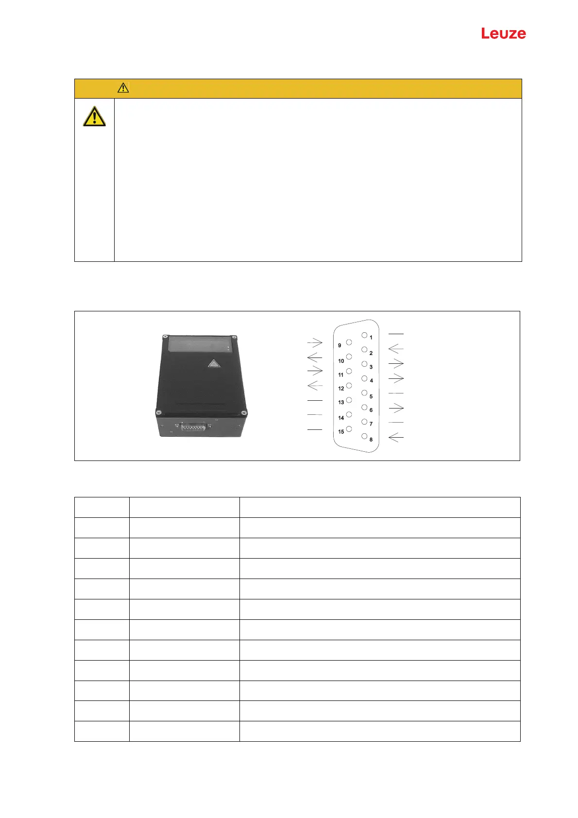
BPS 37 sub-D pin assignments
Figure 6.4: BPS 37 sub-D pin assignments
Connection description
ATTENTION!
Never open the device yourself, as this may compromise degree of protection IP 65.
Before connecting the device, be sure that the supply voltage agrees with the value printed
on the name plate.
Connection of the device and maintenance work while under voltage must only be carried
out by a qualified electrician.
The power supply unit for the generation of the supply voltage for the BPS 37 and the
respective connection units must have a secure electrical insulation through double
insulation and safety transformers according to DIN VDE 0551 (IEC 742).
Be sure that the protective conductor is connected correctly. Fault-free operation is only
guaranteed when the device is properly earthed.
If faults cannot be cleared, the device should be switched off and protected against
accidental use.
GND / RS 232
GND
Reserve
Reserve
TXD/Serv
RXD/Serv
SWOUT1
SSI-Takt-
SWIN1
SSI-Takt+
/Serv
VIN
SSI-Daten+
SSI-Daten-
Reserve
Pin 1 GND Reference ground RS 232
Pin 2 SWIN1 Switching input 1 (+12 … 30VDC)
Pin 3 SSI data+ SSI data line
Pin 4 SSI data- SSI data line
Pin 5 Reserve
Pin 6 SSI clock+ SSI clock line
Pin 7 /Serv Bridge to pin 15: service operation via RS 232 interface
Pin 8 VIN Supply voltage +10 … 30VDC
Pin 9 SSI clock- SSI clock line
Pin 10 SWOUT1 Switching output 1 (max. 100mA)
Pin 11 RXD/Serv RXD signal, RS 232 service interface
Pin 12 TXD/Serv TXD signal, RS 232 service interface