Commissioning
Leuze electronic GmbH + Co. KG BPS 37 27
Current parameter set
In this parameter set, the current settings for all device parameters are stored. When the BPS 37 is in oper-
ation, the parameter set is stored in the EEPROM of the BPS 37. The current set can be stored:
• by copying a valid parameter set from the host computer
• by means of an off-line setup with the PC setup program BPSConfig
The current parameter set is loaded into the memory of the BPS 37:
• always after connecting the supply voltage
• following a software reset
The current parameter set is overwritten by the parameter set with the factory settings:
• by a parameter reset, see ""Online" commands" on page 26
7.3.2 Service operating mode
Setting the required parameters is carried out easiest in the 'Service' operating mode. The Service oper-
ating mode makes the following defined operating parameters available on a separately wired RS 232
interface, independent from the BPS's configuration for standard operation:
• Transmission rate: 9600 baud
• No parity
• 8 data bits
• 1 stop bit
• Prefix: STX
• Postfix: CR, LF
Activate service interface
The service interface is activated via a bridge between the pins 7 and 15 on the 15-pin sub-D connector.
If the BPS 37 is operated with a connection unit, the service interface is activated through a switch in the
connection unit.
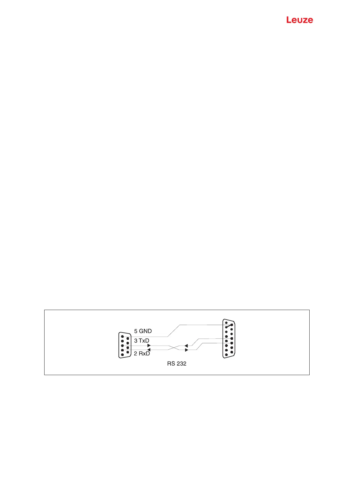
Connection
You can connect a PC or terminal to the BPS 37 via the serial interface and configure the BPS 37 through
this connection. For this, you need a crossed RS 232 interconnection cable (null modem cable) that
provides the connections RxD, TxD and GND. A hardware handshake via RTS, CTS is not supported at
the service interface.
If the BPS is connected to a connection unit, you can use the 9-pin SubD service connector in the connec-
tion unit. For the respective pin assignments, please refer to the data sheet of the connection unit.
Service operating mode
Figure 7.1: Connecting the service interface to a PC or terminal
15 GND
12 TxD
11 RxD
BPSPC
Service