Do you have a question about the Leuze BPS 37 and is the answer not in the manual?
Explains symbols used in the technical description for safety and information.
States compliance with EU standards and directives for BPS 37 series devices.
Describes the BPS 37 series as optical measuring systems using visible red laser light.
Defines improper use of the device beyond its intended application.
Details prerequisites for personnel connecting, mounting, and commissioning the device.
Lists conditions under which Leuze electronic GmbH is not liable for damages.
Provides critical warnings and precautions regarding laser radiation exposure.
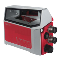
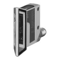
Illustrates and describes the physical components and mounting features of the BPS 37.
Explains the use of bar code positioning systems for automated systems requiring position determination.
Details the three-step process of how the BPS 37 determines position using laser and bar code tape.
Lists key benefits of the BPS 37 system, such as easy mounting and flexible application.
Describes how the BPS 37 can be operated as an individual device via its sub-D connector.
Explains the use of the MS 37 103 for M12 connection technology with the BPS 37.
Provides detailed technical specifications for optical, measurement, electrical, mechanical, and environmental data.
Describes the function of the internal LED indicating supply voltage status.
Presents mechanical dimensions and drawings for the BPS 37 unit.
Shows the graphical representation of the BPS 37's reading field width versus distance.
Lists available accessories, their order numbers, and short descriptions.
Details connection units (MA 4.7/MA 4D.7) and their advantages for installation.
Introduces the BT 56 mounting device for rod mounting the BPS 37.
Mentions the special interconnection cable for connecting BPS and connection units.
Provides instructions for safe packaging, transport, and storage of the device.
Explains the general mounting process and available accessories like the BT 56.
Details the two basic mounting arrangements for the BPS 37 device.
Covers selecting a suitable mounting location and orientation for optimal performance.
Describes how to mount connection units (MA) using mounting plates.
Provides crucial safety warnings before connecting the device and its components.
Details the pin assignments for the BPS 37's 15-pin sub-D connector.
Lists detailed pin functions for the BPS 37's sub-D connector.
Shows connection diagrams for the SSI interface with MA units and directly with BPS 37.
Explains how to connect the protective earth (PE) for proper grounding and EMC.
Describes how to connect the device's switching input and output signals.
Details how the BPS 37 connects using M12 connectors via the MS 37 103.
Shows pin assignments for BPS 37 with MS 37 103 connector hood.
Provides important attention notes for wiring the power supply and switching signals.
Details pin assignments for the PWR IN connector (A-coded M12).
Details pin assignments for the HOST/BUS IN connector (B-coded M12).
Details pin assignments for the SERVICE connector (A-coded M12).
Specifies maximum cable lengths and required shielding for different connections.
Provides guidance on how to disassemble, pack, and dispose of the device.
Lists essential checks and familiarization steps before starting up the device.
Describes how to perform a 'Power On' test and interface checks.
Explains the process of configuring the BPS 37 using software and available options.
Describes the different parameter sets (factory, current, working copy) and their management.
Details the 'Service' operating mode for parameter setting via RS 232 interface.
Explains how to activate the service interface via a bridge or switch.
Guides on connecting a PC or terminal to the BPS 37 for service.
Mentions the LED on the BPS 37 indicating operational readiness.
Describes the status LED on the MS 37 103 connector hood.
Provides step-by-step instructions for installing the BPSConfig software.
Introduces commands and parameters for device control and configuration.
Lists general commands for activating measurement, setting presets, and querying versions.
Explains how parameters are organized into folders for configuration.
Describes settings for activating/deactivating the measurement process.
Covers parameters for preparing measurement values like presets and scaling.
Explains how to define ranges for monitoring measurement values.
Details settings for activation, deactivation, and timing of the switching output.
Describes how the BPS 37 reacts to the application of a 24V signal.
Covers settings for integrating the BPS 37 with control systems via SSI interface.
States that the device requires no operator maintenance other than cleaning.
Provides instructions for cleaning the device's glass window with a soft cloth.
States that repairs must only be done by the manufacturer or authorized service.
Presents the EU/EC Declaration of Conformity for the BPS 37 series.
| Brand | Leuze |
|---|---|
| Model | BPS 37 |
| Category | Valve Positioners |
| Language | English |