Installation
Leuze electronic GmbH + Co. KG BPS 37 23
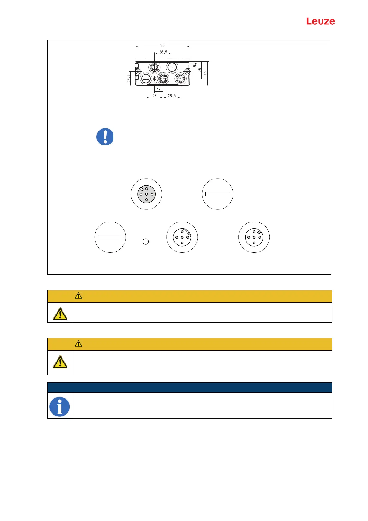
Figure 6.8: Pin assignment of the BPS 37 with MS 37 103
PWR IN - voltage supply and switching input/output
ATTENTION!
Degree of protection IP 65 is achieved only if the connectors and caps are screwed into place!
ATTENTION!
For devices with integrated heating, the supply voltage must be wired with a minimum 0.5mm
2
(recommended 0.75mm
2
) core cross section. It is not possible to loop the supply voltage
through to other loads!
NOTE
Cables with a wire cross section of 0.5 mm² or 0.75 mm² are not available as ready-made
cables from Leuze electronic.
PWR = voltage supply, switching input, switching output
HOST/BUS IN = SSI interface
SERVICE = RS 232 service interface
Note!
The BUS OUT and SW IN/OUT connections are sealed
with caps.
Socket
(A-coded)
Connector
(B-coded)
Connector
(A-coded)
SWIN
CLK+
SWOUT
3
2
1
4
GND
VIN
FE
3
2
1
4
1
2
3
4
/SERV
RXD
TXD
GND
FE
D-
CLK-
D+
SW IN/OUT
HOST/BUS IN PWR
SERVICE
BUS OUT
STATUS