i Series e Users Guide Page 7 of 35
LIT-31903-00
Dimmer Numbering – Sequential vs. Phase Balanced
Regardless of configuration, dimmer slots are always numbered sequentially from the top to the bottom of
the rack. However, the default patch can be altered based on the setting of JP6. When in sequential mode,
dimmers are patched from the top to the bottom of the rack, the top dimmer module with dimmer slot
positions 1 & 2 being patched to control input numbers 1 & 2. The second module, dimmer positions 3 & 4
are patched to control input channels 3 & 4. This sequence continues until you reach the end of the rack.
In a phase balanced configuration, the dimmer slot number remains the same, however, the default patch is
that dimmer positions 1 & 2 are patched to control channels 1 & 2, 1/3 of the way down the rack where at the
top module of phase B is located, are control channels 3 & 4. 2/3 of the way down the rack where the top
module of phase C is located, you find patched control channels 5 & 6. The goal of a phase balanced
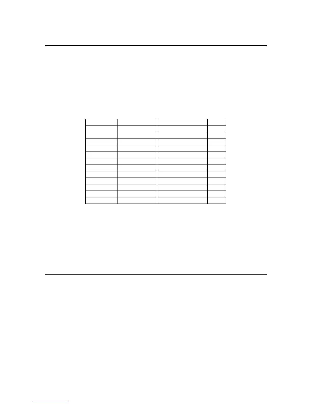
system is to better distribute sequential loading across all three phases. To further illustrate this point, see
the chart based on an i24e cabinet below:
Dimmer Slot Sequential Patch Phase-Balanced Patch
Phase
1,2 1,2 1,2 A
3,4 3,4 7,8 A
5,6 5,6 13,14 A
7,8 7,8 19,20 A
9,10 9,10 3,4 B
11,12 11,12 9,10 B
13,14 13,14 15,16 B
15,16 15,16 21,22 B
17,18 17,18 5,6 C
19,20 19,20 11,12 C
21,22 21,22 17,18 C
23,24 23,24 23,24 C
With jumper JP6 on the backplane removed, the rack responds as a sequential rack, and with JP6 installed,
the rack responds as a phase balanced rack for all standard patches. The upper and lower control modules
are completely independent of each other, with completely different custom patches and configuration
information, which allows them to be connected redundantly, or to two completely different control sources.
The outputs of both control modules pile onto each other in a highest takes precedence or HTP fashion.
The remainder of this manual details the specific functions of the various indicators on the control
module(s), dimmer modules and features that are accessible with the hand held terminal option.
1.1 Violet i Light indicator (not on i24)
The violet i Light indicates the current operating status of the rack. The indications are as follows
i LIGHT ON : A dimmer is on in the rack. The fan is on medium speed.
i LIGHT OFF : All dimmers are off in the rack. The fan is off.
i LIGHT FLASHING : At least one dimmer in the rack is in an over-temp or other
warning condition. The fan is operating at full speed.