User Manual for LEVIFLOW
®
LFIF-06 Flowmeters
www.levitronix.com
PL-4511-00, RevA, DCO# RD
2.4 Overview of Parameter Configuration
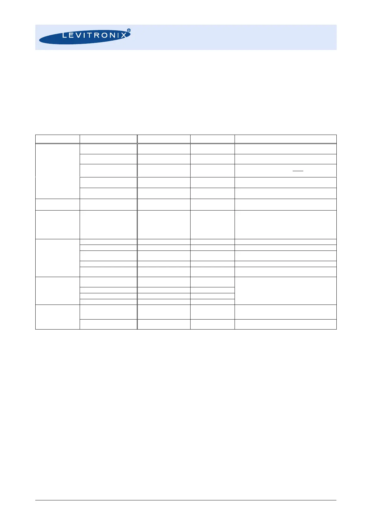
Table 3 shows the standard (“Default”) and possible parameter configurations of the flowmeter. This user
manual is dealing with the standard configuration. For setting up other configurations the LEVIFLOW
®
Configuration Software is needed. Consult the “Configuration-SW User Manual” (Levitronix
Doc.# PL-4501-
00) for more detailed description.
Note: The LFIF-06 flowmeter needs configuration software version V1.34 or higher.
xx = 06
(accord. Sensor size)
xx indicates the measurement ID of the tube.
Default Values:
LFIF-06 = 10 L/min
Flow cut to 0 below this percentage of full-scale
If cutoff 0% is chosen, negative flow becomes visible
Kinematic Visc. = Dynamic Visc. / Density
Not implemented for LFIF-06 flowmeter.
With the LFE-E.3 cable the current can be converted into
0 – 10 V voltage.
Flow alarm High
Flow alarm Low
Vol. counter Pulse
Measurement Error
Flow as Frequency
Digital Output Off
- Upper flow limit detection
- Lower flow limit detection
- Pulse per volume
- Error signal (empty sensor etc.)
- Flow as Frequency output (100% of full-scale = 1 kHz)
- Set digital output off
Can be used to get tolerance to noise.
Alarm setting In percentage of full-scale.
N.O. = normally open
N.C. = normally closed
Alarm setting In percentage of full-scale.
N.O. = normally open
N.C. = normally closed
Volume counter enable
(activation box)
These are settings for volume detection (integration of
flow).
Has to be active for the option “Vol. Counter Pulse” on
digital output.
Volume counter pulse length
Measurement
Error Settings
Instant Measurement Error
Ignore Time
During this time instant measurement errors are ignored.
If an instant measurement error stays active for longer
time than this time, measurement error arises.
Flow Level on Measurement
Error
Signal level of analog output and flow, when
measurement error arises
Table 3: Overview of parameters
 Loading...

