User Manual for LEVIFLOW
®
LFIF-06 Flowmeters
www.levitronix.com
PL-4511-00, RevA, DCO# RD
3 Installation
3.1 Electrical Installation
3.1.1 Overview and Preparation
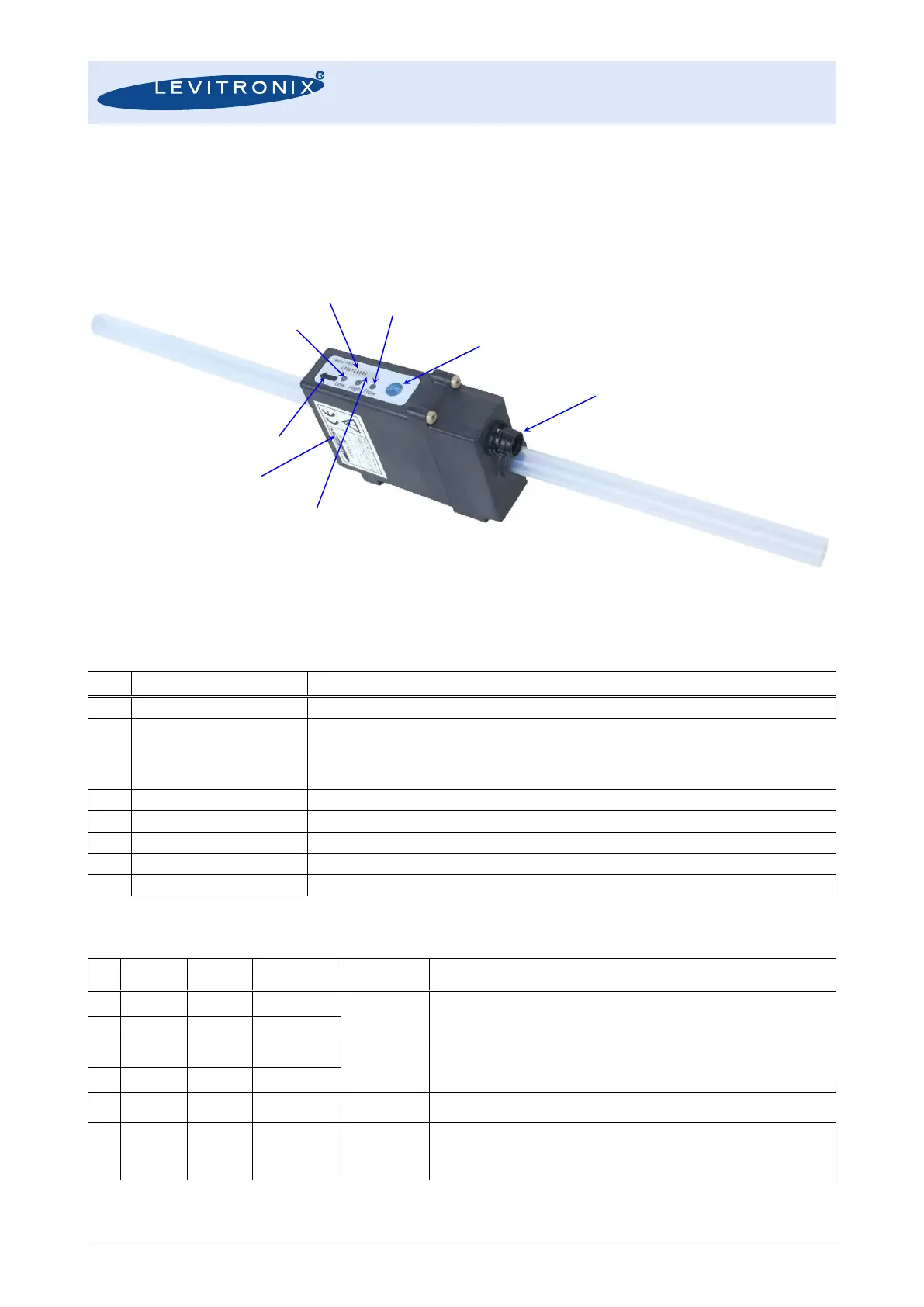
Figure 4: Integrated flowmeter LFIF-06
Supply and electrical interface (see Table 5 for specifications).
For offset elimination with zeroing. To be pressed for more than 3 seconds to start zeroing.
Zeroing process duration is about 20 seconds.
Indicates status of flow measurement is blinking with frequency proportional to flow (~20 Hz
at 100% of full scale). At zero flow it is constantly on.
Indicates high flow alarm (see Table 3).
Indicates low flow alarm (see Table 3).
Indicates flow direction.
Unique serial number for traceability.
Contains article number and part name.
Table 4: Standard specifications of interface items on flowmeter
Specification and Description.
Supply Voltage: 24 VDC ±10%
DC24V- to be connected to earth.
Modbus protocol for communication with PC.
Current: 0 – 20 mA (load resistance < 500 Ohm), Reference is DC24V-
Note: Cable LFE-E.3 contains integrated resistor for conversion 0 – 10V output.
Open collector with nominal load DC 30V/10mA, Reference is DC24V-
1
Note: Cable LFE-E.2 contains integrated pull-up resistor for electrical definition of
default signal.
Note: see Table 3 for origin of errors.
Table 5: Standard interface specification of flow sensor connector and cable LFE-E.1/2
Note 1: Cable LFE-E.2 contains integrated pull-up resistor for electrical definition of default signal.
6: „Arrow“ Label for
Flow Direction
7: Label with Serial Number
 Loading...

