User Manual for LEVIFLOW
®
LFS Flowmeters
www.levitronix.com
PL-4502-00, Rev11, DCO# 18-107
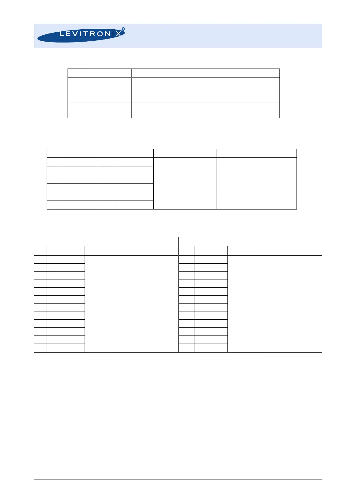
24 VDC ± 10%
(See Table 7 for current specifications)
Field Ground. See note in installation Section 3.2.2
RS485 with MODBUS protocol
Digital communication in a sensor array or configuration with configuration SW.
Table 11: Standard configuration of bus connector for LFC-6C and LFC-6CIO
4 - 20 mA
(0 – 20 mA configurable)
Load resistance < 600 Ohm
Flow reading with 4-20 mA. Standard full scale
flow range of each sensor model.
Flow rate signal.
Update rate is 5 ms per channel.
Table 12: Standard configuration of analog output connector for LFC-6CIO
Maximum rating:
30 VDC, 20 mA
(open collector)
- Parameter: Flow Alarm High
- Setting: 105% of full scale
- Normally opened
Contact is made, when 105% of
full scale flow rate is exceeded.
No-voltage
contact or
transistor open
collector.
Zero Adjustment
Is needed, if zero adjustment
wants to be triggered by PLC or
when volume counter function is
used (integration of flow with
volume detection)
Table 13: Standard configuration of digital in/output connector for LFC-6CIO
1. Check if all parts are delivered as shown in Figure 17. For every configuration (single
converter as shown in Figure 17a and multi converter array as in Figure 17b) a termination
box (resistance to terminate the RS485) and a connector box (wiring) is needed.
2. For communication with RS485 check the address settings of the potentiometers on the front
panel of the converter (see Figure 17d). The total address of the first channel is:
“High ADRS” x 10 + “Low ADRS” x 1
3. The LEVIFLOW
®
Configuration Software can be used to debug and configure the flowmeter
over the RS485. For communication with RS485 the MODBUS protocol can be requested at
Levitronix
.
 Loading...

