EasyManuals Logo

Levitronix LEVIFLOW LFSC-i06X User Manual

Levitronix LEVIFLOW LFSC-i06X
19 pages
To Next Page IconTo Next Page
To Previous Page IconTo Previous Page
Page #11 background imageLoading...
Page #11 background image
User Manual for LEVIFLOW
®
LFSC-iX Flowmeters
www.levitronix.com
PL-5001-00, Rev00, DCO# 21-084
11
CAUTION
The analog outputs of the PLC of the flowmeter need an insulated power source on
the user side, which is separated from the flowmeter supply. Non insulated power
sources may damage the sensor.
Sensor Connector
ICS-2.2 and ICS-2.4
OEM Cable
Specification
Standard Configuration / Description
PIN
Designation
PIN
Wire Color
3
11
Supply DC+
11
Red
Voltage: 12-24 VDC ±10%,
Current: max. 120 mA
Inrush current: max. 0.3 A for 2ms
Supply.
3
Supply Ground
3
Yellow
1
RS485 +
1
White
RS485 with MODBUS Protocol.
Communication to PC, user panel and other devices. Multi-
flow sensor arrays with fieldbus.
2
RS485 -
2
Brown
7
Current Output 1+
7
Violet
4-20 mA or 0-20mA configurable
Max. load resistance 180 .
Note: Needs insulated power source on user
side.
2
Flow reading with 4-20 mA (0-20mA configurable).
1
Standard full scale flow range of each sensor model.
Note: ICS-2.4 cable contains an integrated power source for
analog Current Output 1.
6
Current Output 1
Return Line
6
Blue
4
Current Output 2+
4
Grey
4-20 mA or 0-20mA configurable
Max. load resistance 180 .
Note: Needs insulated power source on user
side.
2
For future use
5
Current Output 2
Return Line
5
Pink
8
Digital Output 1
8
Grey-Pink
Max. 24 VDC/100 mA
Reference is Supply Ground.
Measurement error
Other designations can be configured.
1
9
Digital Output 2
9
Blue-Red
Max. 24 VDC/100 mA
Reference is Supply Ground.
Flow alarm high
Other designations can be configured.
1
12
Digital Input
12
Black
5-24 VDC, 4.7 kOhm input shunt.
Reference is Supply Ground.
Zeroing input.
Other designations can be configured.
1
10
Shielding
10
White-Green
and Shield
Connected to flowmeter housing.
To be connected to protective earth of user interface.
2
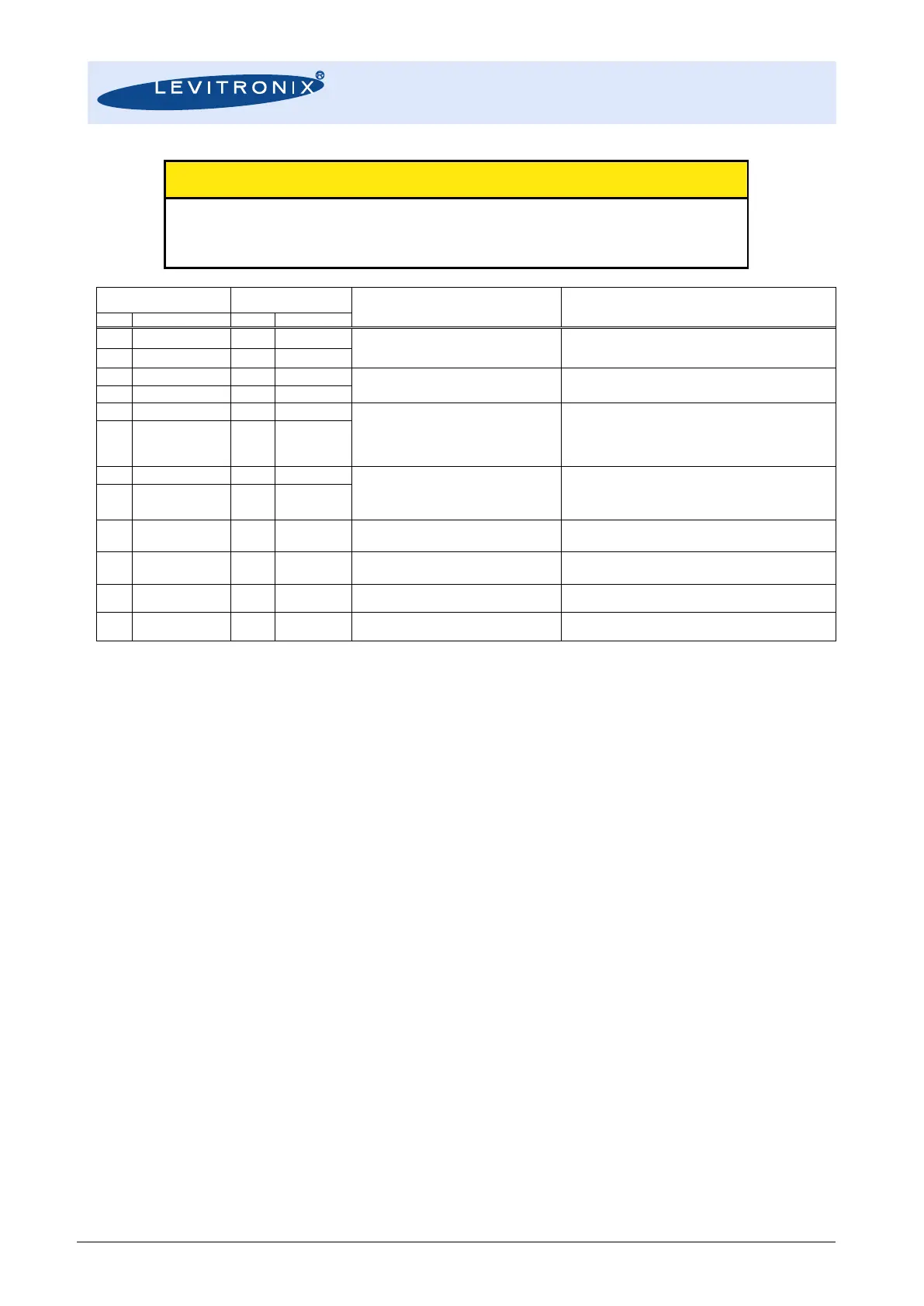
Table 5: Standard configuration of electrical interface connector
Note 1: Configuration with Levitronix
®
Service Software. Note 2: See schematics Figure 9 for example of interfacing. Note 3: Wire size is 12x 0.14 mm
2
.
3.3 Instructions for Electrical Installation
1. Remove the DC power and all cables from the flowmeter before any installation work is done.
2. For operation with the user panel LUI-B.1 or with a PC attach the cables as shown in Figure 3 and
Figure 4.
3. For operation with the OEM cable ICS-2.2 or ICS-2.4, attach the necessary wires (AWG 14-26)
according to the pin specifications in Table 5. Strip the sheath approximately 3 mm from the wires
end. Insert core into the cable terminal to the end and tighten the screw. Confirm that the wires are
securely fixed by pulling it gently by hand.
4. Alternatively, the terminal of the ICS-2.2 or ICS-2.4 cable can be removed to assemble another
connector like wall-mountable circular connectors for cabinet mounting.
5. If another AC/DC power supply than the one offered by Levitronix
®
is used, than the specifications
in Table 5 shall be considered (voltage range, consumption current and start-up current).
6. For usage of a fuse at the power input a 200 mA slow-blow type is recommended considering the
inrush (start-up) current of the flowmeter (see Table 5).
7. Before powering on check again all wiring connections. Confirm that the terminals are securely
fastened and that there is no possibility of short circuit.
8. When applying power, the controller needs about 10 seconds for a start-up procedure to be ready.
In order to get stable temperature and signals for converter and sensor 30 minutes must be waited
after power-on.
9. After start-up a Zeroing is recommended. Assure that the sensor is filled completely with the
according fluid, free of bubbles and that zero flow is realized. Section 4.1.3 explains the zeroing
possibilities.
10. The Levitronix
®
Service Software can be used to debug and configure the flowmeter over the RS485.
For communication with RS485 the MODBUS protocol can be requested at Levitronix
.

Questions and Answers:

Question and Answer IconNeed help?

Do you have a question about the Levitronix LEVIFLOW LFSC-i06X and is the answer not in the manual?

Levitronix LEVIFLOW LFSC-i06X Specifications

General IconGeneral
BrandLevitronix
ModelLEVIFLOW LFSC-i06X
CategoryMeasuring Instruments
LanguageEnglish

Related product manuals