4-106 Service Manual
7525-xxx
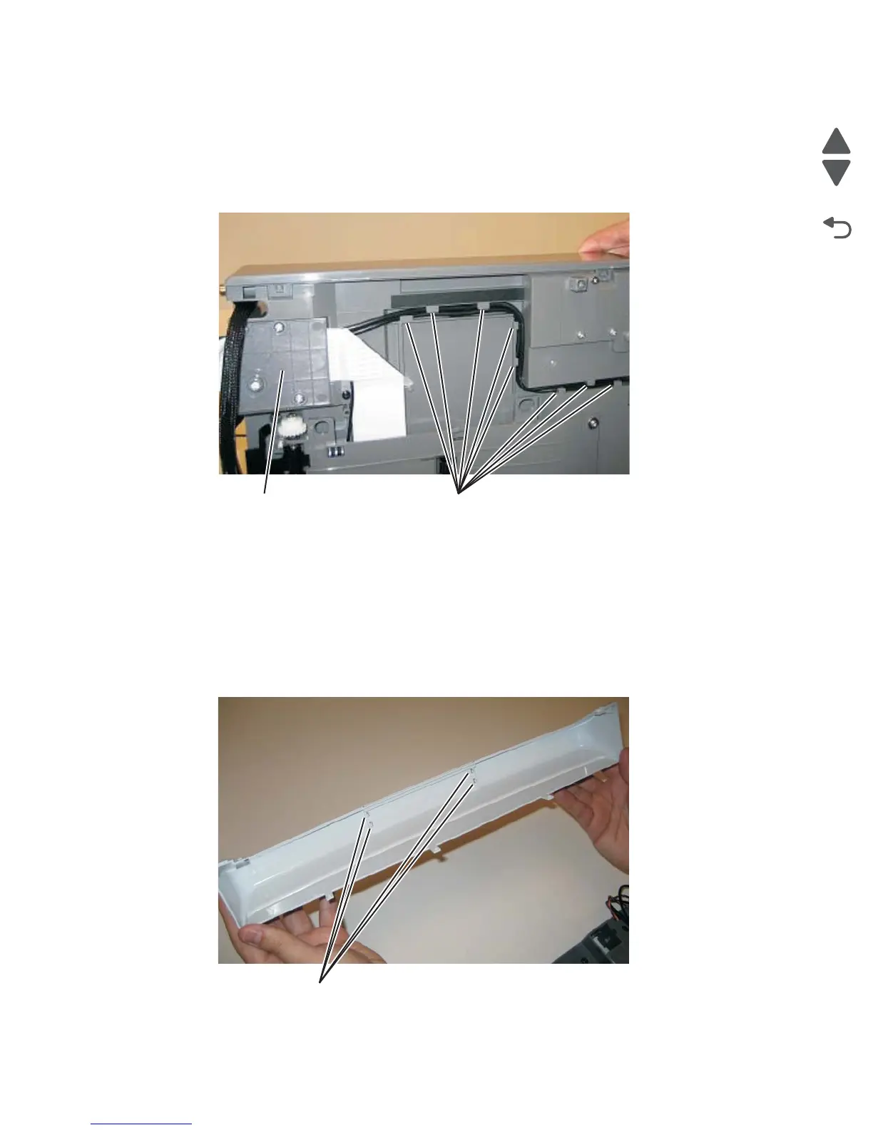
Op panel cable
1. Remove the operator panel bezel cover.
2. Remove the operator panel. See “Operator panel removal” on page 4-103.
3. Remove the flatbed assembly. See “Flatbed removal” on page 4-77.
4. Remove the CCD cable cover.
5. Unroute the operator panel cable through the tabs (B).
Warning: When replacing the op panel and USB cables, the cables must be routed in the exact same route
with no overlapping of the cables. Failure to do so can result in the crimping of the cables. In
addition, the redrive unit on the scanner might not make proper contact with the redrive rolls on the
top cover. This could result in a paper jam under the flatbed unit.
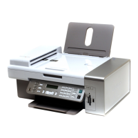
Logo cover
1. Remove the op panel bezel cover. See “Op panel bezel removal” on page 4-105.
2. Use a flatbed screwdriver to depress the four tabs (A) securing the logo cover to the op panel bezel cover.