GA 05.130/3.02 - 05/98
Description
6
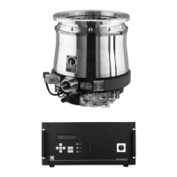
Front panel
Main switch
9-pin connecting socket for the RS232 interface
7 short-stroke keys
1 backlit LCD with 2 lines, each 16 characters, 8 mm
character height
1 green/red STATUS LED
1 green COM LED (communications interface)
1 green MAIN LED (line supply voltage)
Rear panel
X1 25-pin D socket connector for remote monitoring
and open-loop control
X7.2 9-pin D connector for RS232
X10 3-pin Hirschmann connector for the connection to
the mains supply
X24 64-pin Harting socket connector for internal sen-
sors and magnetic bearing connection
X26 10-pin Harting socket connector for the motor
connection
X31 25-pin Harting socket connector for the TMS and
purge valve connection
X33 3-pin terminal strip, 24 V output voltage (e.g. for the
power failure airing valve)
F1 Fuse for mains power supply (only MAG.DRIVE L2)
F2 Fuse for power supply of the active magnetic bea-
ring (only MAG.DRIVE L2)
F3 Fuse for the heating (TMS)
1 or 2 protective earth terminals
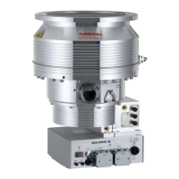
1.4 Function and design of
the MAG.DRIVE
The MAG.DRIVE L and MAG.DRIVE L2 electronic con-
verters are used to drive the MAG turbo-molecular
pumps.
The electronic converters convert the single-phase line
supply voltage into a three-phase DC voltage to control
and monitor the electronically-commutated DC motor. It
also evaluates measured signals and controls (open-
loop and closed-loop) the pump functions.
The temperature management system (TMS) and the
magnetic bearing control system are integrated into the
converter. The TMS regulates the pump temperature by
switching the heating on/off or cooling the pump. The
magnetic bearing control system actively controls the
pump rotor in five axes (closed-loop control).
All parameters required for pump operation and the
listed faults and operating hours are stored in a non-vola-
tile memory in the pump. When the converter is switched
on, the data are loaded into the converter from the pump.
The outputs of the electronic converter are no-load and
short-circuit proof.
The electronic converter can be connected via its serial
interface to external open-loop control and monitoring
devices. More detailed information on the serial interface
and the interface protocol are provided in the Option
Manual “MAG.DRIVE serial interface”.
For remote control via control connector X1 we recom-
mend that either a relay or optocoupler is used to provi-
de electrical isolation.
Housing
The converter is supplied with a closed housing. It can
be installed in a 19” cabinet
 Loading...