l1
§
()
:a;
§
g:
:::s
,...
(11
....
.,
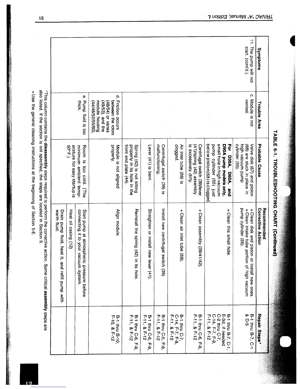
Symptoms
11.
The pump will not
start. (cont'd.).
TABLE 6-1. TROUBLESHOOTING CHART ,"' .......... .
Trouble Area
c.
Module is not
vented.
d.
Friction occurs
between
the
rotors
(48/54) or vanes
(49/53), and the
module housing
(44/46/52/55/60) .
e.
Pump fluid is too
thick.
Probable Cause
Valve disk
(67)
and piston
(68) are stuck in place in
high vacuum pump
cylinder
(55).
For D30A, D60A, and
D90A pump models only,
small hole in high vacuum
pump
cylinder
(55)
just
below
piston(68)
isclogg
Centrifugal switch
(39)/Iever
(41
)/spring
(42)
assembly
is excessively dirty.
Air inlet tube
(69)
is
clogged.
Centrifugal switch (39) is
malfunctioning.
Lever
(41)
is bent.
Spring
(42)
is not sitting
properly in its hole in the
front end plate (44).
Module
is
not aligned
properly.
Room is too cold. (The
minimum
ambient
temp-
erature
for
easy startup is
50°F.)
+ Clean disk and piston or install new ones.
+ Clean intake tube portion of high vacuum
pump cylinder (55).
+ Clean this small hole.
+ Clean assembly (39/41142).
+ Clean air inlet tube (69).
Install new centrifugal switch (39).
Straighten or
install new lever (41).
Reinstall the spring (42) in its hole.
Align module.
Start pump
at
atmospheric pressure before
connecting it to your vacuum system.
Heat oil casing (12)
Drain pump fluid, heat it, and
refill pump with
warm fluid.
Repair
B-1
thru B-7,
C-1
&
0-5
B-1
thru B-7, C-1,
E-3d; if needed
C-2 thru
Co?,
C-14, F-?, F-9,
F-11, & F-12
B-1
thru C-6,
F-9,
F-11, & F-12
B-1
thru
Co?,
C-14, F-?, F-9,
F-11,&F-12
B-1
thru C-5, F-9,
F-11, & F-12
B-1
thru C-6,
F-9,
F-11, & F-12
B-1
thru C-6,
F-9,
F-11, & F-12
B-1
thru B-10,
F-10, & F-12
·This
column contains the disassembly steps required to perform the corrective action. Some critical assembly steps are
also listed.
If the section is not specified, the steps are located in Section 5 .
+ Use the general cleaning instructions at the beginning of Section 5-E.
 Loading...


