Chapter 4. FUNCITION BLOCK
4 - 4
4.3 Remote Function Block
4.3.1 Module write : (G3F-DA3V/G3F-DA3I : DAR33WR, G4F-DA3V/G4F-DA3I : DAR3WR,
G4F-DA2V/G4F-DA2I : DAR2WR, G6F-DA2V/G6F-DA2I : DAR62WR)
Module write function block of the Single type is a program for the use in performing for a channel of D/A
conversion module and setting a digital value to be converted into a D/A conversion.
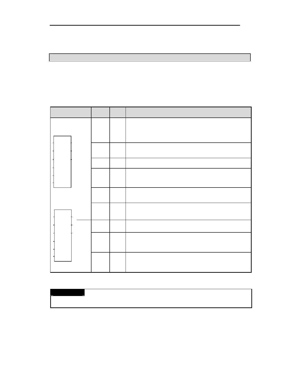
Function
block
I/O Variable
Data
type
Descriptions
REQ BOOL
Function Block Execution Request Area on Rising Edge.
- The execution of write function block is requested in this area.
- If the status to be connected with this area is satisfied on the program operation and input
condition changes from low(0) to high(1), function block initialization for the module is
executed.
NET_
NO
USINT
The location number of the slot on which the transmission module of the master station is
mounted.
-Setting range: 0 to 7
ST_NO USINT
Station number of the communication module which a remote I/O station has.
- Setting range : 0 to 63
BASE USINT
Base Location Number Area
- The base No. on which A/D conversion module is mounted is written on this area.
- Setting range : G3F -DA3V,G3F-DA3I,G4F-DA3V,G4F-DA3I,G4F-DA2V,G4F-DA2I : 0 to 3
G6F-DA2V,G6F-DA2I : 0
SLOT USINT
Slot Location Number Area
- The slot No. on which A/D conversion module is mounted is written on this area.
- Setting range: 0 to 7
Input
DATA
INT
[Array]
*Note1
Input Data Type Specification Area
-Input digital data type for each channel is specified in this area.
-Setting range : 0 ~ 4000
NDR BOOL
When function block execution is completed with no error, 1 is written. During the scan which
the execution condition has been made, 1 is continuing and at the next scan. 0 is written.
ERR BOOL
Error Data Display Area
- When error occurs during function block initialization, 1 is written and the operation comes to
stop. During the scan which the execution condition has been made, 1 is continuing and at
the next scan, 0 is written.
G3F-DA3V/DA3I
G4F-DA3V/DA3I
G4F-DA2V/DA2I
G6F-DA2V/DA2I
Output
STAT USINT
Error Code Display Area
- When error occurs during function block initialization, the error code number is written.
REMARK
Note 1: Array number of data type means the whole number of channels and channel number.
Array number of G3F-DA3V/G3F-DA3I/G4F-DA3V/G4F-DA3I is 8 and array number of G4F-DA2V/G4F-DA2I/G6F-DA2V/G6F-DA2I is 4.
ST_N
BASE
SLOT
DATA
DAR(3)3WR
STAT
REQ
NET_
ST_N
BASE
SLOT
DATA
DAR(6)2WR
STAT
REQ
NET_
ERR
NDR