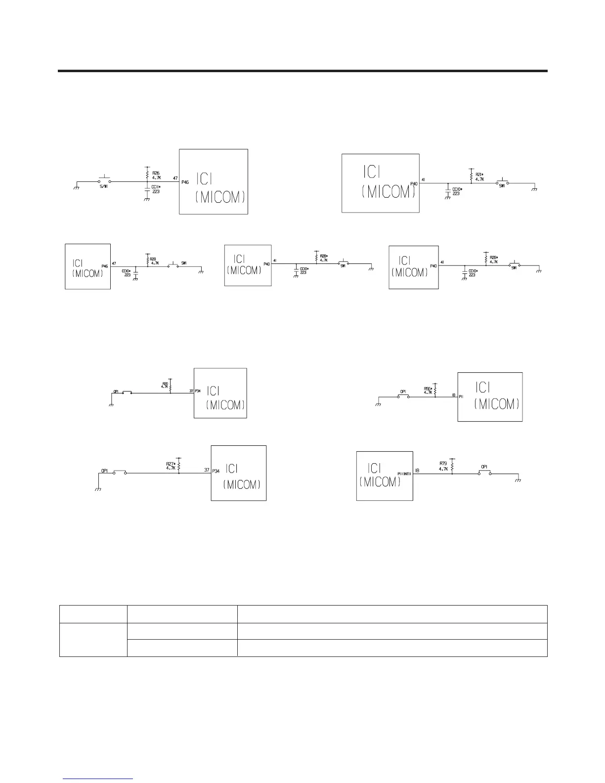
1-6. Switch entry circuit
The following circuits are entry circuits for sensing signal form test S/W, electronic single motor damper reed S/W for
examining refrigerator.
1-7. Option designation circuit (model separation function)
The above circuits are used for designating separation by model as option and notifying it to MICOM. Designation of option
by model and the application standards are as follows:
u These circuits are accurately pre-adjusted in shipment from factory and so you must not additionally add or remove
option.
EXPLATION FOR MICOM CIRCUIT
- 46 -
<GC-B/C207: 88-LED>
<GC-B/C207: Bar, Dot-LED>
<GC-P/L207: 88-LED> <GC-P/L207: Dot-LED>
<GC-P/L207: Bar-LED>
<GC-B/C207: 88-LED> <GC-B/C207: Bar, Dot-LED>
<GC-P/L207: 88-LED> <GC-P/L207: Dot-LED>

 Loading...