For motor driving method, rotation magnetism is formed at coils wound on each phase of motor and stator and so motor
becomes to rotate if applying “High” signal to the IC8 (TA777AF) at the MICOM PIN 33 and outputting “High”, “Low” signal
by step numbers fixed through MICOM PIN 34 and 35,.
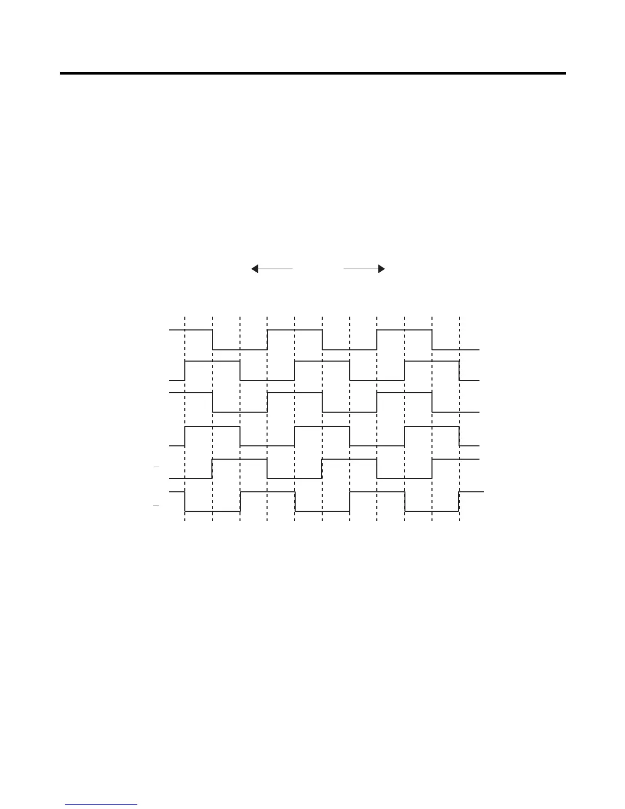
Explanation) For driving method of the stepping motor, send signals in the cycle of 3.33 mSEC using terminal of MICOM
PIN 33, 34 and 35 as shown in wave form of the following part.
These signals are output to the output terminal (No.10, 11, 14, 15) via the input terminal (No. 3, 6, 8) of the
IC10 (TA7774F) as IC for motor driving. Output signals allow motor coils wound on each phase of stator to
form rotation magnetic field and the motor to rotate. Inputting as below figure to the input terminal (INA, INB)
as IC (TA7774AF) for motor driving allows motor coils wound on each phase of stator to form rotation
magnetic field and the stepping motor damper to rotate
EXPLATION FOR MICOM CIRCUIT
- 48 -
 Loading...