21
General Installation Guidelines
Due to our policy of continuous product innovation, some specifications may change without notification.
©LG Electronics U.S.A., Inc., Englewood Cliffs, NJ. All rights reserved. “LG” is a registered trademark of LG Corp.
GENERAL INSTALLATION GUIDELINES
Mounting of Indoor Unit Installation Plate
Follow the procedure and best practices below when mounting the
Wall-Mounted indoor unit’s plate to a wall.
Procedure
1. Before installation of the plate, confirm the position the screw
types (A or B) between chassis and installation plate.
2. Mount the installation plate horizontally by aligning the centerline
using a leveling tool.
3. Use provided screws when mounting the plating.
• If mounting the unit on concrete wall, use field supplied anchor
bolts.
4. Choose what side (left or right) to install the piping, and then
observe the left and right rear piping clearances when drilling into
the wall, as shown in Figures 9, 11, 12.
Select location carefully. Unit should be anchored to a strong wall to pre-
vent unnecessary vibration.
• When choosing a location for the wall mount plate, be sure to take
into consideration routing of wiring for power outlets within the wall.
Contacting wiring can cause serious bodily injury, or death.
• Use caution when drilling holes through the walls for the purposes
of piping connections. Power wiring can cause serious bodily injury,
or death.
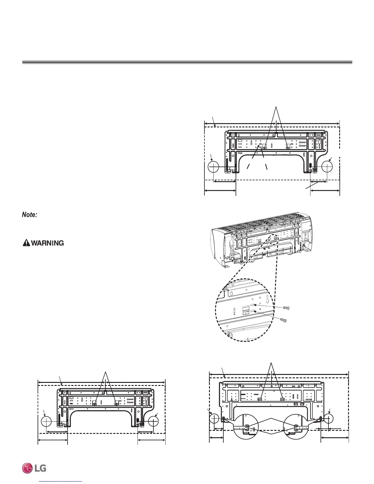
Mounting Installation Plate to Wall (091HSV3, 121HSV3, 181HSV3)
Ø2-19/32
4-
27/32
3- 24/32
Left
rear piping
Installation Plate
Place a level on raised tab
Unit Outline
8-
17/32
6-
29/32
17-13/32 17-13/32
Unit: Inch
Right
rear piping
Ø2-19/32
Figure 9: Installation Plate Screws - 091HSV3, 121HSV3
Unit: Inch
Ø2-19/32
Ø2-19/32
2 -11/16
2-3/16
Right rear
piping
Left rear
piping
Installation Plate
Measuring Tape
Measuring Tape
Hanger
Place a level on raised tab
Unit Outline
8-3/32
4-3/32
18-3/32 22-13/32
Ø2-9/16
4-7/8
A Type : 3-3/4
B Type : 6-3/4
A Type B Type
Right rear piping
Left rear piping
Place a level on raised tab
Unit
Outline
8-9/16
6-15/16
Unit: Inch
A Type : 17-7/16
B Type : 17-1/8
A Type : 17-7/16
B Type : 17-5/16
Ø65Ø2-9/16
Installation Plate
Refer to “Drilling Piping Hole in the Wall” on page 22 as
you follow procedure to install the plate.
A-Type
B-Type
Figure 10: Installation Plate Screws
Figure 11: Installation Plate - 091HSV3, 121HSV3
Figure 12: Installation Plate - 181HSV3
 Loading...