56
6LQJOH=RQH+LJK(I¿FLHQF\6WDQGDUG([WHQGHG3LSHDQG0HJD:DOO0RXQW,QVWDOODWLRQ0DQXDO
Due to our policy of continuous product innovation, some specifications may change without notification.
©LG Electronics U.S.A., Inc., Englewood Cliffs, NJ. All rights reserved. “LG” is a registered trademark of LG Corp.
ELECTRICAL WIRING
Indoor Unit Electrical Connections
Overview - Connecting Indoor Unit Electrical Wiring
The general guidelines for connecting electrical and communication cables to the indoor unit are the same for each of the Single Zone Wall
Mounted indoor units, however, the actual connections on the terminal block will differ. See each illustration for the Single Zone unit model
that you are wiring for correct contact on each terminal block. Depending on your indoor unit, the location of the terminal block on the indoor
unit might vary slightly from the images shown in this section.
• Be sure that main power to the unit is completely off before pro-
ceeding with these steps.
• Follow all safety and warning information outlined at the beginning
and throughout this manual. Failure to do so may cause bodily injury.
Procedure
Be sure there is no power going through the Single Zone system before
proceeding with these connections as there be a risk of electrical shock
and bodily injury.
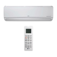
1. At the bottom panel of the indoor unit, unsnap the latches which
cover the phillips screw heads as shown in Figure 87.
• Normally, there are three (3) screws on the panel, however your
indoor unit model may differ.
2. Using a phillips head screwdriver, remove the screws from the
bottom panel of the indoor unit and set aside (Figure 88).
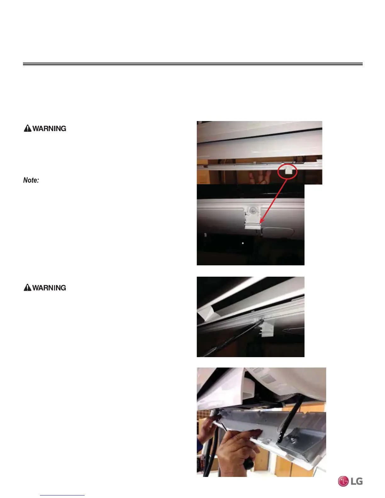
3. Remove the bottom panel (Figure 89).
• Removal is necessary to gain access to the terminal block which is
situated at the bottom of most indoor units.
• Note that the electrical/communications wiring is usually routed
through the back/bottom of the indoor unit (through a knockout
panel) as shown on the next page (Figure 90).
4. Using a screwdriver, connect the wires as shown on the next
page (Figure 91).
• Each wire should be securely attached to the terminal block.
• Pay attention to the location/connection of the green/yellow ground
cable.
Figure 87: Latch over Screws on Bottom Panel, Indoor Unit
Figure 88: Remove Screws from Bottom Panel
Figure 89: Remove (and Reattachment) Bottom Panel
• Follow all safety and warning information outlined at the beginning
and throughout this manual. Failure to do so may cause unit failure.
• Some units might require you to remove the Control Cover from
the terminal block area. Most Control Covers are attached with a
phillips screw head.
• Connect the electrical cable to the indoor unit by connecting the
wires to the terminals on the control board individually according to
the outdoor unit connection. Be sure that the color of the wires at
the outdoor unit along with the terminal numbers are the same as
those for the indoor unit.
 Loading...