39
General Installation Guidelines
Due to our policy of continuous product innovation, some specifications may change without notification.
©LG Electronics U.S.A., Inc., Englewood Cliffs, NJ. All rights reserved. “LG” is a registered trademark of LG Corp.
GENERAL INSTALLATION GUIDELINES
Piping Materials and Handling
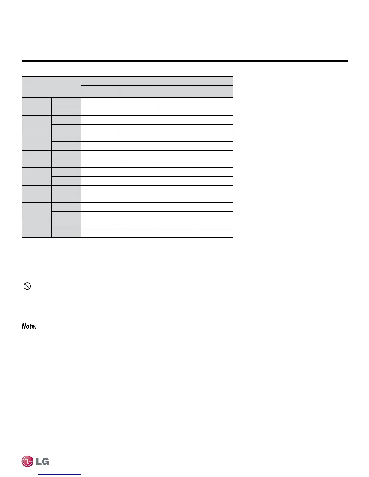
Anticipated Linear
Expansion (LE) (inch-
es)
Nominal Tube Size (OD) inches
1/4 3/8 1/2 3/4
1/2
R
1
6 7 8 9
L
2
38 44 50 59
1
R
1
9 10 11 13
L
2
54 63 70 83
1-1/2
R
1
11 12 14 16
L
2
66 77 86 101
2
R
1
12 14 16 19
L
2
77 89 99 117
2-1/2
R
1
14 16 18 21
L
2
86 99 111 131
3
R
1
15 17 19 23
L
2
94 109 122 143
3-1/2
R
1
16 19 21 25
L
2
102 117 131 155
4
R
1
17 20 22 26
L
2
109 126 140 166
Pipe Bends
When bending soft copper, use long radius bends. Refer to the "Radii of Coiled Expansion Loops and Developed Lengths of Expansion
Offsets” table for minimum radius specifications, as shown above.
In-line Refrigeration Components
Components such as oil traps, solenoid valves, filter-dryers, sight glasses, tee fittings, and other after-market accessories are not permitted
on the refrigerant piping system between the outdoor unit and the indoor unit.
Duct-free Single Zone systems are provided with redundant systems that assure oil is properly returned to the compressor. Sight-glasses and
solenoid valves may cause vapor to form in the liquid stream.
Over time, dryers may deteriorate and introduce debris into the system. The designer and installer should verify the refrigerant piping system
is free of traps, sagging pipes, sight glasses, filter dryers, etc.
Field-provided Isolation Ball Valves
LG allows the installation of field-supplied ball valves with Schrader ports at each indoor unit. Full-port isolation ball valves with Schrader
ports (positioned between valve and indoor unit) rated for use with R410A refrigerant should be used on both the liquid and vapor lines.
If valves are not installed and a single indoor unit needs to be removed or repaired, the entire system must be shut down and evacuated.
Position valves with a minimum distance of three (3) to six (6) inches of pipe on either side of the valve, and placed between six (6) and
twelve (12) inches from the run-out pipe to the upstream main pipe. If ball valves are installed closer to the indoor unit, a section of pipe
becomes a dead zone when the valves are closed where oil may accumulate.
Table 18: Radii of Coiled Expansion Loops and Developed Lengths of Expansion Offsets
 Loading...