184 185
_TROUBLE SHOOTING GUIDE BOOK _
16.2 Failure Cause
16.3 Precautions of Replacement
16.4 Check Point after Replacement
1. High voltage (T-N more than 484V, N phase wiring fault) → CH50
2. Rainwater inflow by Control box / Front Panel / Service port open, Control box screw loosening
3. Part short by foreign substance
4. Defective Fan motor / PCB / Diode / Resistance / Capacitor / Regulator
1. Be sure to use the main PCB suitable for the model (Check P/No)
2. Be sure to turn off the power and wear insulated gloves before touching the PCB.
3. Use box or bag only for PCB.
4. Be sure to apply thermal grease.
5. When IGBT screw is fastened, it should be fastened two times.
6. If on-boarding is required after replacement, check the program and
EEPROM C/Sum (especially when using an alternate Main PCB)
1. Check whether there is any abnormality when the cycle is stabilized at cooling or heating mode.
2. Check current Hz control according to target Hz
3. Over current error check (CH29)
4. Check that fan 1 and 2 are properly connected.
5. Check that the target high / low pressure is reached.
17.1 Failure Judge Method
17.2 Failure Causes
1. Error code check
Error Code Error diagnosis
- · Checking restart after power reset
CH05, CH53
· Even after checking 220V connection condition for main SMPS
power supply
CH76, CH107
· Indoor/Outdoor communication PCB connection harness(24pin), Main
- External PCB communication harness(10pin) connection condition
CH05, CH53, CH104,
CH237, CH238
· Even after checking the connection condition of indoor and outdoor
communication lines (shield wire, unshield wire)
2. Communication PCB check
1. Part short (by foreign substance, moisture)
2. Resistance / Capacitor / Micom / Comm. IC defect
3. Connector & Housing Pin wrong connection
4. PCB Fault
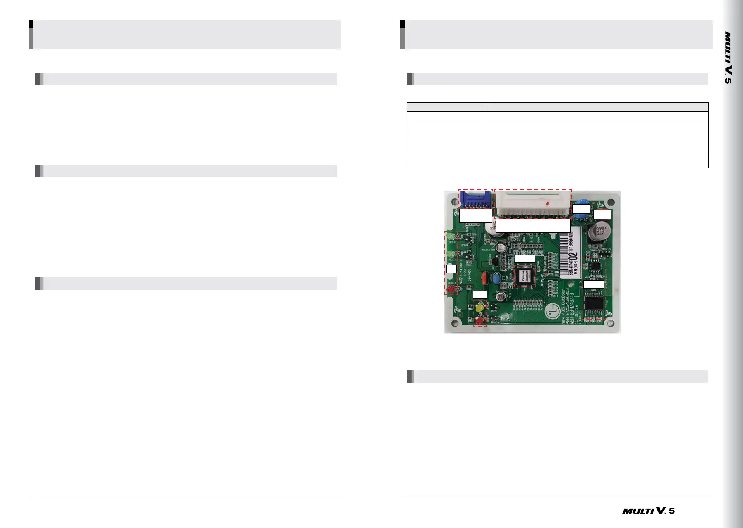
17. Communication PCB
Connector
(CN-Write)
Connector
(485 Comm. PCB <-> Main PCB)
Y-Cap
BEAD
통신 IC
MICOM
LED
LED
Basic PartBasic PartBasic PartBasic Part

 Loading...


