210 211
_TROUBLE SHOOTING GUIDE BOOK __
4. Function Mode
It is a function to control the cooling / heating limit through the switch of cool & heat selector and ODU
This is used to prevent heterogeneous operation and unnecessary energy wastage.
4.1 Cool & Heat selector
■ Setting the function
Function Option
Cool & Heat selector Fn 1 oFF, op1~op2
■ Option Selection
Switch Control Function
Switch (Up) Switch (Down) oFF op1 op2
Right side (On) Left side (Left) Not operate Cooling Cooling
Right side (On) Right side (On) Not operate Heating Heating
Left side (On) - Not operate Fan mode Off
• If "On" & "op1" is selected, the following three operating scenarios are possible:
1) Cooling mode
The right side of the upper switch + The right side of the lower switch.
2) Heating mode
The right side of the upper switch + The left side of the lower switch.
2) Fan mode
The left side of the upper switch (The position of the lower switch is irrelevant)
Mechanical refrigeration is locked out and the IDU fans are allowed to operate.
Left Right
Upper
Lower
■ Detailed information
• This function is used with heat pump only.
• Heating, Cooling, Fan Only, Dry modes are a change in the setting impact.
• Cool & Heat selector information
-
IDU control without central controller.
-
Select operation mode : Cooling, Heating, Fan mode.
-
Mode lock for cooling & heating mixing error-proof during the change of season.
-
The Cool & Heat selector switch consists of two toggle switches mounted over/under. The upper
switch is two-position and manually locks out heating and cooling operation allowing Fan only or
allows heating or cooling operation depending on the position of the lower switch. The bottom
switch is two-position and manually sets the position of the outdoor unit's reversing valve. If the
left side is depressed, the valve is in the cool position. If the right side is depressed, the valve
is in the heat position.
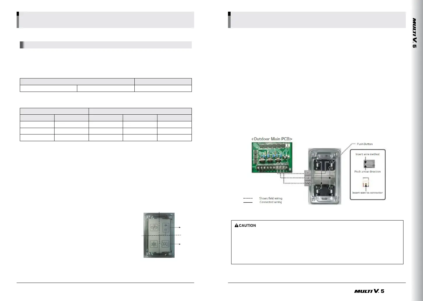
• Wiring Diagram
· Ask an authorized technician to setting a function.
· If do not use a function, set an off-mode.
· If use a function, first install a Cool & Heat selector.
· Simultaneous model can not be used.
· Communication line length can be maximum 300m, use Communication line as thick as 1.25mm.
· This function is disabled during central controller connection.
(Central control mode lock function is prior to this function)
Basic PartBasic PartBasic PartBasic Part

 Loading...


