89
ACCESSORIES INSTALLATION
ENGLISH
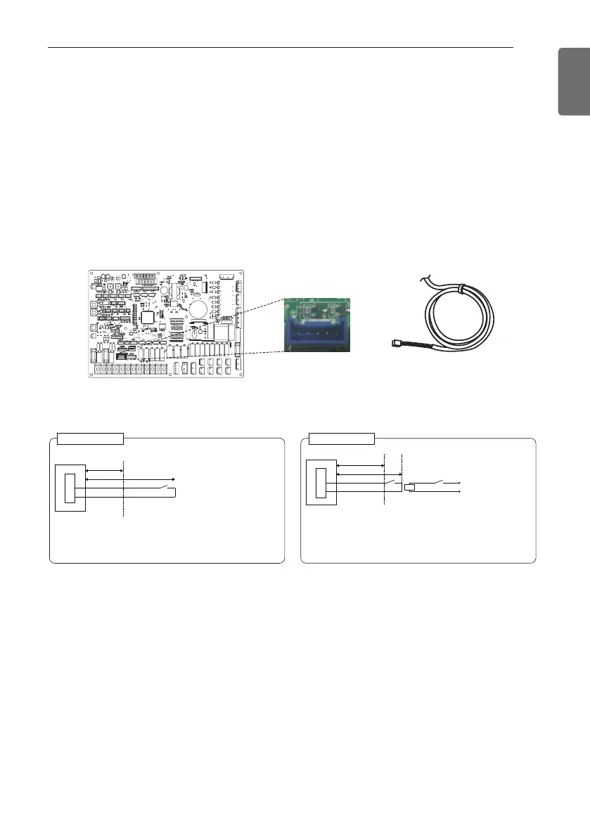
External Controller - Setting up programmable digital input
operation
If you require to control depending on external digital input(ON/OFF), connect cable to indoor
PCB(CN_EXT).
Follow below procedures step 1 ~ step 4.
Step 1. Check if the power of the unit is turned off.
Step 2. Disassemble front panels and distinguish control box(Indoor) of the unit
Step 3. Connect the external controller to PCB(CN_EXT) completely.
Step 4. Connect the cable and field installation part.
CN_EXT
Indoor PCB
Adapter Cable
• SW : Single pole switch
- Select a part with contacts
for extremely low amperage
- DC 5 V ~ 12 V is used at the
contact point
- Switch load is approximately
0.5 ~ 1 mA
• Control cable
- Cable size : 22 to 26 AWG
- Don’t extend the cable more
than 10 meters
Indoor Unit
PCB
Supplied Part
Field
Installation Part
SW
0.5 m
Max 10 m
CN_EXT
• X : Relay (a point of contact, fixed DC 0.5 ~ 1 mA)
• SW : Distance ON/OFF switch
• Control cable (Indoor unit to Relay Circuit)
- Cable size : 22 to 26 AWG
- Don’t extend the cable more than 10 meters
Installation example #2
Indoor Unit
Supplied Part
X
0.5 m
Max 10 m
X
Relay Circuit
Power
supply
of relay
SW
PCB
Field Installation Part
CN_EXT
Installation example #1
 Loading...