the steering drive shaft is subjected to great impact, and
energy is absorbed by the deformation of the steering column
or the dislocation of the steering drive shaft.
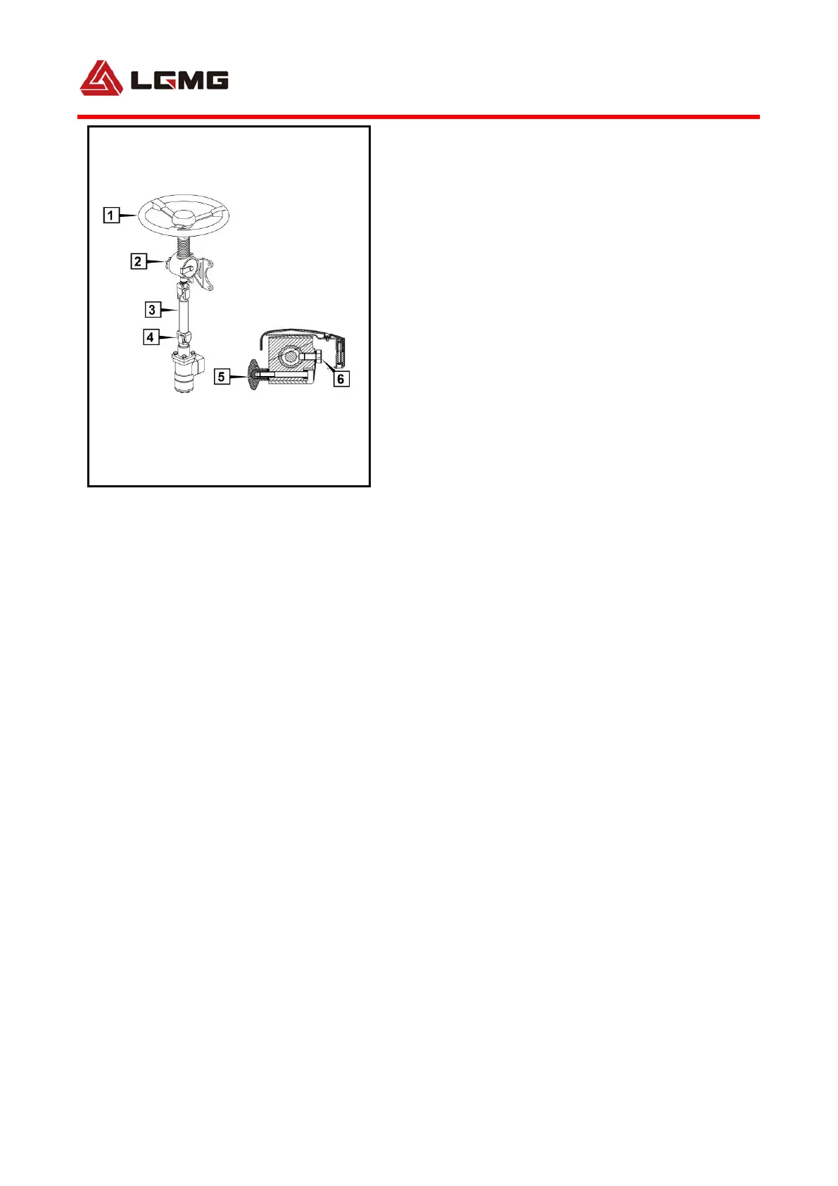
Steering control system is of continuous and adjustable
type. With this system, the height range of steering wheel is
±25mm, and the angle range is ±5°.
Specific adjusting method: Unscrew adjusting handle
as shown, adjust steering wheel 1 to appropriate operating
position, and tighten the adjusting handle .
4.7.2 Hydraulic power steering system
Full-hydraulic steering gear, pilot valve, hydraulic oil
pump, hydraulic oil tank, steering cylinder, hydraulic
pipeline, etc. The steering cylinder is φ80.
1) Full-hydraulic steering system construction
The steering pump is a vane pump. The engine is
directly connected with a power takeoff at the position of
engine power take off, and keeps running. The steering pump
sucks oil from the hydraulic oil tank and outputs
high-pressure oil to a pilot valve P opening. The pilot valve
has following 5 openings: P, EF, CF, and Ls. Excessive
hydraulic oil of the steering system returns to the oil tank via
EF opening. CF opening is connected with full-hydraulic
steering gear P opening to provide high-pressure oil to the
steering gear. Ls opening is connected with steering gear Ls
opening as a control line. When the steering wheel drives the
steering gear to rotate, the steering gear Ls opening provides