60 Appendix 4 Refrigerant, Hydraulic And Electrical Connections
Liebert.CRV Series Air Conditioner User Manual
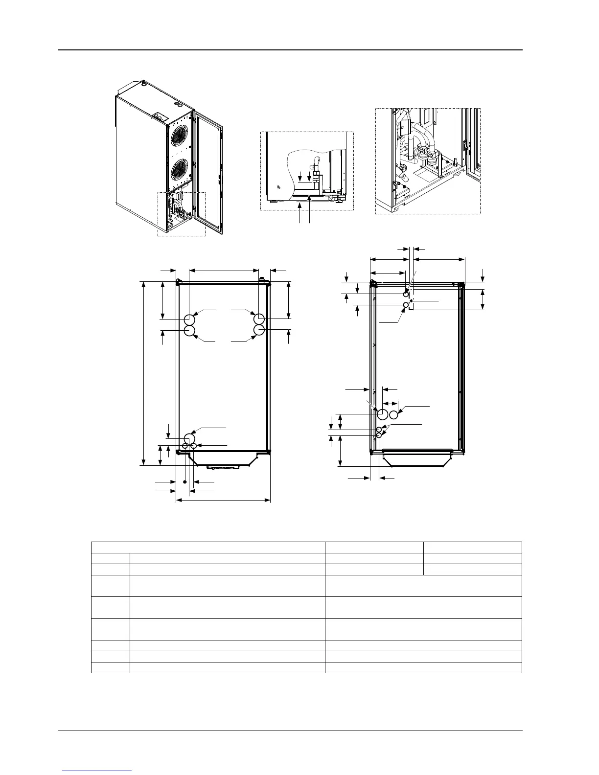
Rear
view
155
105
EC-HV
EC-LV
HF
DP
OWC
IWC
IWC
EC-LV
HF/HD
EC-HV
OWC
Top connections
83
440
77
69 237
1175
69 242
45
127
600
56
54
83
Bottom connections (possible with raised floor)
69
74
76.5
98
28
247.5
324.5
44130
225.5
35
97
199
55.5
CD or
DP
Figure 12 CR020RW, CR035RW connections (unit: mm)
Table 10 Refrigerant and hydraulic connections for water cooled units
Unit connection CR020RW CR035RW
IWC Water to condenser inlet 32mm GAS F 32mm GAS F
OWC Water from condenser outlet 32mm GAS F 32mm GAS F
CD
Condensate drain
Attention: with pump, CD is connected with HD, see DP
ID 20mm
HF Humidifier feed
12.7mm GAS-F for top connections,
19mm GAS F for bottom connections
HD
Humidifier drain
Attention: with pump, CD is connected with HD, see DP
ID 22mm
DP Pump drain 12.7mm GAS F
EC-HV
Electrical supply – high voltage Hole, Φ63mm
EC-LV Electrical supply – low voltage Hole, Φ28mm