Appendix 4 Refrigerant, Hydraulic And Electrical Connections 61
Liebert.CRV Series Air Conditioner User Manual
155 105
44083 77
237
69
242
69
1175
127
45
600
83
54
56
EC-LV
EC-HV
HF
DP
OCW
ICW
225.5
247.5
324.5
28
ICW
OCW
HF/HD
74
69
76.5
98
97
35
199
55.5
CD or DP
EC-LV
130
44
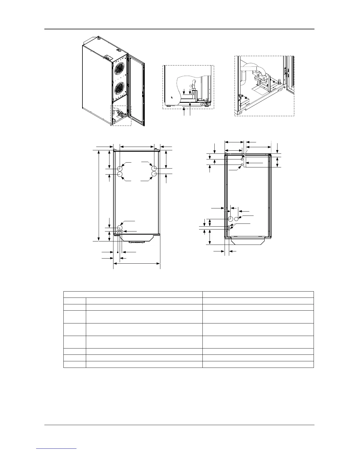
Rear view
Top connections
Bottom connections (possible with raised floor)
Figure 13 CR040RC connections (unit: mm)
Table 11 Refrigerant and hydraulic connections for chilled water units
Unit connection CR040RC
ICW Chilled water inlet 32mm GAS F
OCW Chilled water outlet 32mm GAS F
CD
Condensate drain
Attention: with pump, CD is connected with HD, see DP
ID 20mm
HF Humidifier feed
12.7mm GAS-F for top connections,
19mm GAS F for bottom connections
HD
Humidifier drain
Attention: with pump, CD is connected with HD, see DP
ID 22mm
DP Pump drain 12.7mm GAS F
EC-HV
Electrical supply – high voltage Hole, Φ63mm
EC-LV Electrical supply – low voltage Hole, Φ28mm