Chapter 2 Mechanical Installation 9
New Liebert_DM Series Air Conditioner User Manual
4. Avoid locating multiple indoor units close to each other. This can result in crossing air patterns, uneven loads and
competing operation.
5. Do not install additional devices (such as smoke detectors) over the cabinet for facilitating routine maintenance.
Figure 2-6 indicates the installation location of the indoor unit.
Not recommended location
location
Recommended
Figure 2-6 Installation location of the indoor unit
2.4.3 Installation Procedure
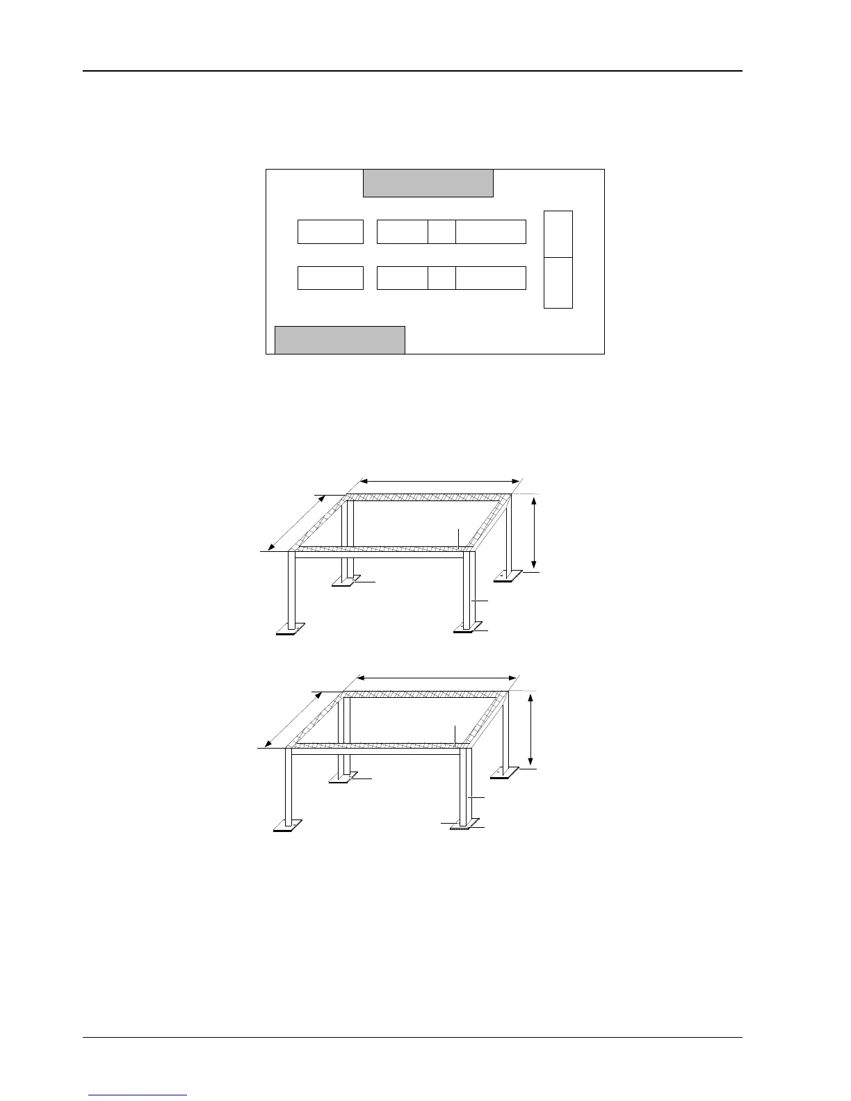
1. Secure the mounting base made by yourself on the selected location. The outline and dimensions of the mounting
base are shown in Figure 2-7.
510
385
Rubber cushion
(8mm ~ 10mm thickness)
Steel plate (60 60 4)
H > 150
Rubber cushion
(8mm thickness)
Angle iron (30 30 3) or
square tube (25 25
3)
Mounting base of DME07kW indoor unit
600
500
H > 150
Installation hole for
expansion bolt (M6 50)
Rubber cushion
(8mm ~ 10mm thickness)
Steel plate (60 60 4)
Rubber cushion
(8mm thickness)
Angle iron (30 30 3) or
square tube (25 25 2)
Mounting base of DME12kW indoor unit
Figure 2-7 Mounting base (unit: mm)
2. Lay a rubber cushion with 8mm ~ 10mm thickness on the mounting base, as shown in Figure 2-7.
3. Place the indoor unit onto the mounting base and secure it.
4. Rotate the grilles to regulate the airflow direction of the indoor unit, and the regulating angle is 45°, as shown in
Figure 2-8.