Chapter 6 System Maintenance 39
New Liebert_DM Series Air Conditioner User Manual
3. Connect the power cable correctly.
4. Restore the humidity setpoint to the original setting.
6.2.6 Power SPD
Power SPD
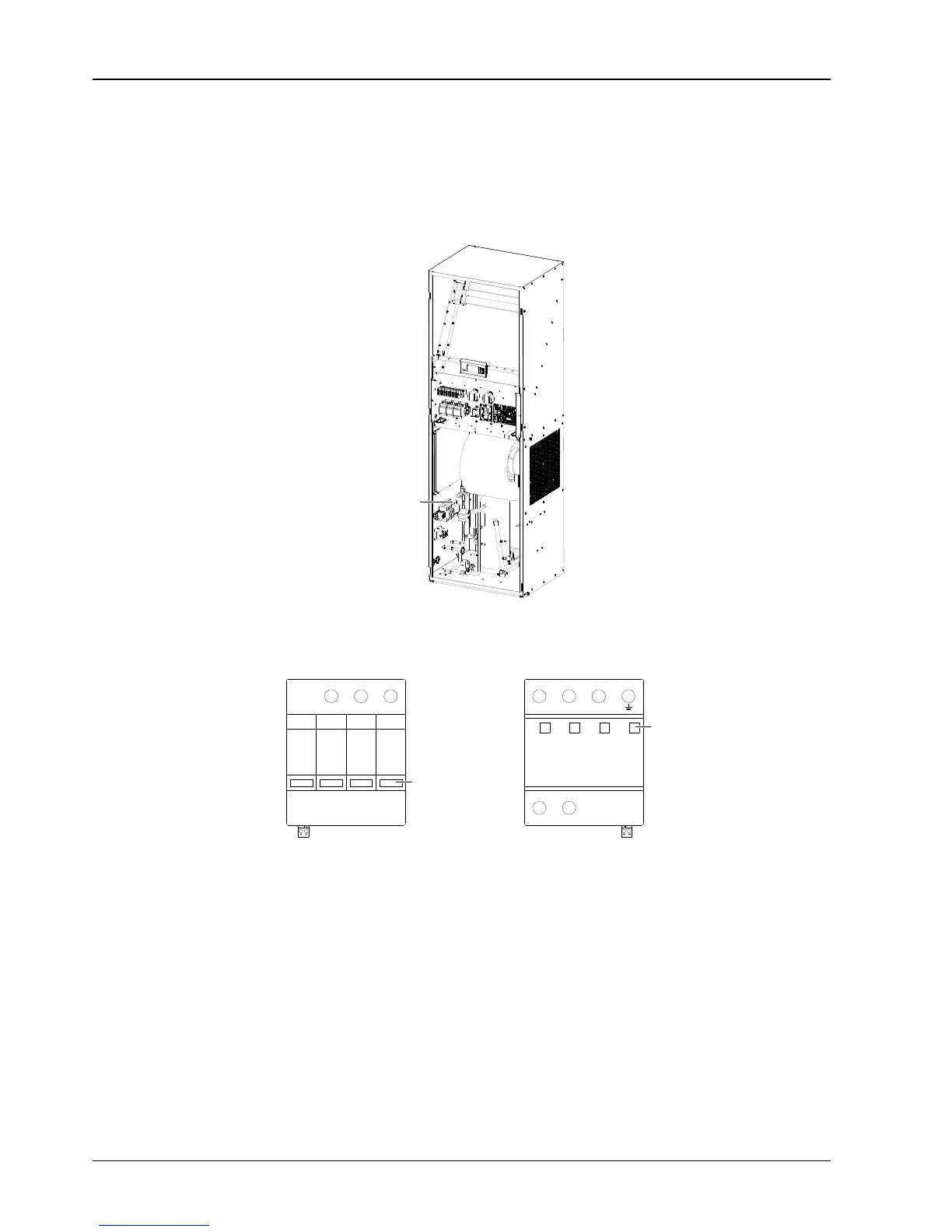
The position of the power SPD is shown in Figure 6-6.
Figure 6-6 Power SPD position
The power SPD has four status indicators, as shown in Figure 6-7. The status indicators are green in normal
operation; they become red upon failure.
Figure 6-7 Status indicator position of power SPD
The power SPD does not need special maintenance. It needs regular check for non-loosening and normal status
indicating.
If any one of the following phenomena appears, the power SPD has failed and it needs to be replaced immediately.
1. Any indicator of the power SPD turns red.
2. The customer alarm 1 is generated (see SPD (Customer 1 terminal) in 3.5.1 Connecting Control Terminals).
6.2.7 Thermal Expansion Valve
The thermal expansion valve keeps the evaporator supplied with enough refrigerant to satisfy load conditions. Its
proper operation can be determined by measuring the superheat level. The correct superheat setting is 5.6°C to
8.3°C (10°F to 15°F).