Chapter 3 Electrical Installation 21
New Liebert_DM Series Air Conditioner User Manual
SPD (Customer 1 terminal)
When the PIN1 and PIN2 of the customer 1 terminal (control terminal) J19 are not connected to SPD signal, they can
connect with an alarm signal except for the AC system. Any outer alarm signal with NO dry contact can be connected
with the customer terminal. After the outer alarm signal is connected, you should set the corresponding customer
alarm information in micro-processing controller. For details, refer to Customer Alarm in 5.6.2 Alarm Menu. If no
alarm signal is connected, the input state of the customer terminal is the same as the settings. If the outer alarm is
generated, the input state of the customer terminal is different from the settings. The AC system will generate an
audible alarm and LCD screen on the micro-processing controller will display the corresponding alarm information. If
a computer using Emerson host monitoring software is connected, the alarm will be displayed on the computer too.
If the power SPD is configured, the PIN1 and PIN2 of the customer 1 terminal J19 have been connected with alarm
signal of power SPD in factory and the alarm is set to be normally closed (NC).
General alarm terminal
The general alarm relay, connected with 19 and 20 on the terminal block (see Figure 3-7), has a set of NC dry contact,
which can be set to normally closed by software. When serious alarm is generated, the contact is closed. This can be
used to send a remote alarm, sending signals to the building management system or dialing the paging system
automatically.
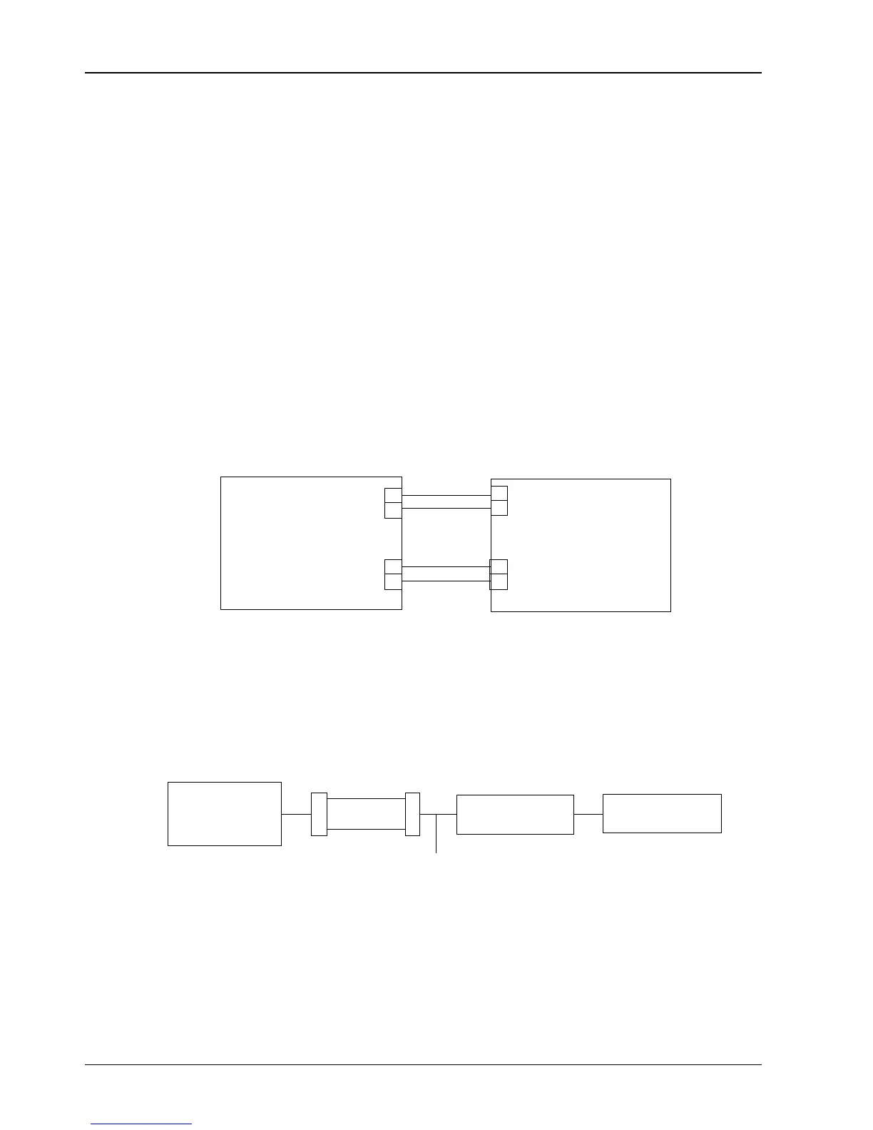
Lead/standby switch over and requirement terminals
The PIN17 and PIN18 of the lead/standby switch over terminal and the PIN7 and PIN8 of the requirement terminal
J19 (see Figure 3-7) are used to connect two AC units working in master-slave mode. The connection mode is shown
in Figure 3-8.
Figure 3-8 Connection in master-slave mode
3.5.2 Connecting Monitoring Port Cable
The RS485 port of the Liebert_DM indoor unit is located on the J39 terminal on the PCB (see Figure 3-6), use a
twisted-pair communication cable to connect it with the upper machine.
Multiple Liebert_DM ACs can realize simultaneous multi-units monitoring through RS485 bus. Taking RDU-Cooling
host monitoring software developed by Emerson for example, Figure 3-9 introduces a networking mode of RS485 bus
monitoring two AC units simultaneously.