20 Chapter 3 Electrical Installation
New Liebert_DM Series Air Conditioner User Manual
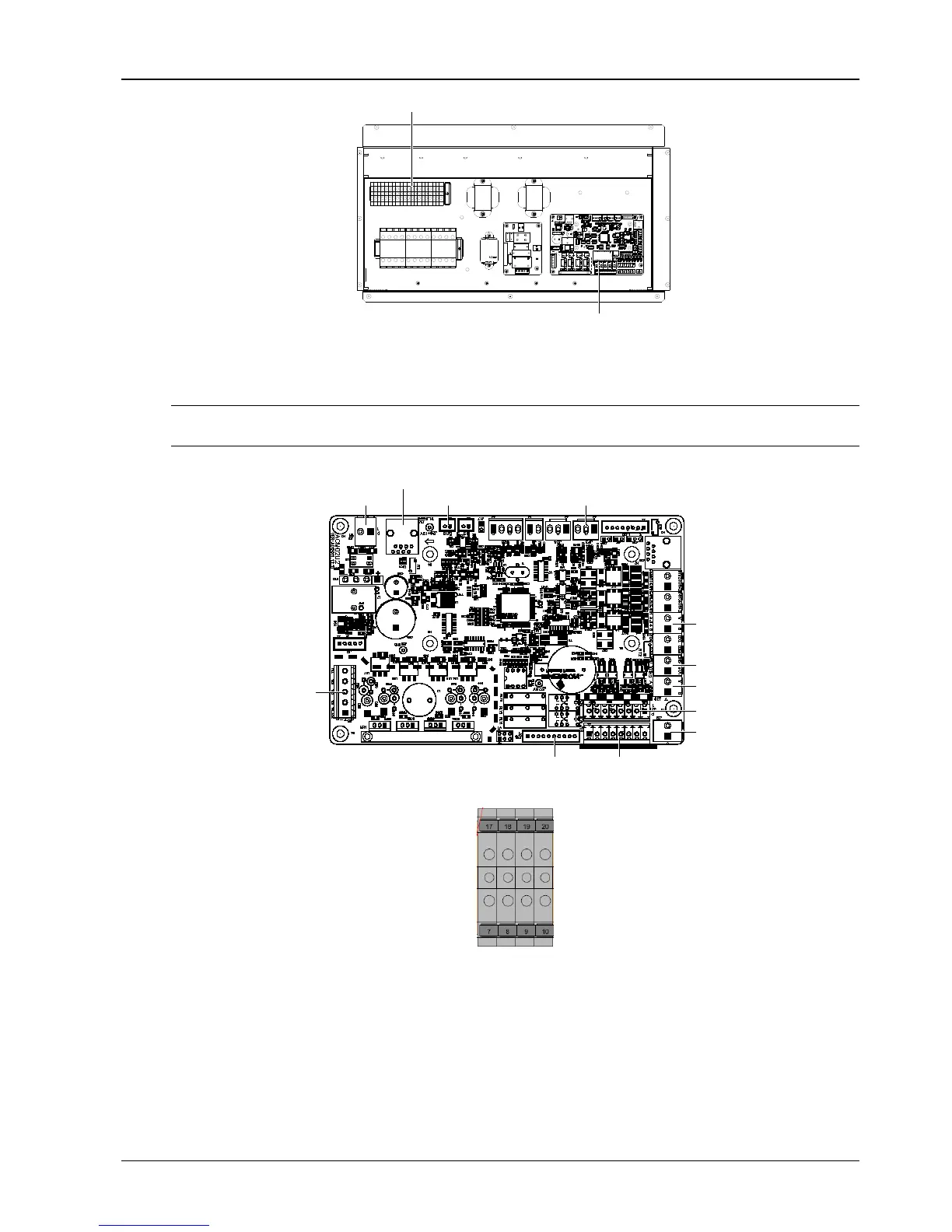
Control terminals on the terminal block
Control terminals on the PCB
Figure 3-5 Control terminal position
The control terminals on the PCB are shown in Figure 3-6; the control terminals on the terminal block are shown in
Figure 3-7.
Note
Before connecting the control cables, connection personnel must take anti-static measure.
ON
J13 single board power input
J28 output of electrical heater and so on
J18 silicon controlled
output to contactor
and so on
J34 temperature and humidity detection board
J23
pressure sensor
J14 monitoring
J12 display panel power
J39 display panel data cable
J21 input of high pressure
switch
and so on
J31 DI
input power
J19 input of remote on/off and so on
J16EC fan control
Figure 3-6 Control terminals on the PCB
Figure 3-7 Control terminals on the terminal block
Remote shutdown
The PIN5 and PIN6 of the remote shutdown J19 can be used to remotely control the unit ON/OFF status, stopping
the unit operation upon special moment. If the input of remote shutdown terminal is shorted and the AC unit power is
switched on, the AC unit outputs normally. If the terminal is open, the AC unit will stop outputting. The remote
shutdown terminal has been shorted before delivery. If the control cable of remote shutdown needs to be connected
in site, remove the short cable and connect the outer controller to the remote shutdown terminal.
 Loading...


