Figure 3-10 Energy-saving card
Use 4-core shielded cables with a recommended cable diameter not less than 20AWG (0.52mm
2
) to connect the
energy-saving card. Make sure that the two ends of the shielded layer and the energy-saving card are grounded
reliably to increase the anti-interference ability. The grounding cable should not exceed 10cm, and the cable size
should be above 2mm
2
. Make sure that all connections are tight.
Use the energy-saving card according to the following steps:
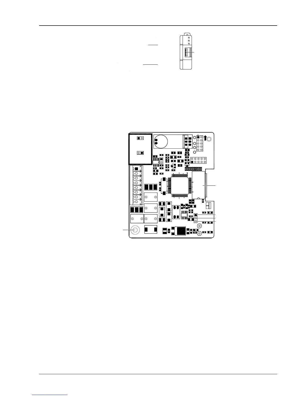
1. Open the front plate of the energy-saving card plastic shell and take out the energy-saving card board along the
card slot inside the plastic shell. The board is shown in Figure 3-11.
Figure 3-11 Energy-saving card board
2. Short terminals J8.1 and J8.2 in furthest energy-saving card and short terminals J8.2 and J8.3 in other cards.
3. Ground the cards reliably.
4. Put the energy-saving card into the shell along the card slot and replace the front plate.
5. Use 4-core shielded cables to connect the Liebert_DM control board on back of the front door of the indoor unit to
12V, GND, CANH and CANL interfaces of the energy-saving card, and snap the accessory magnetic buckle on the
shield cable close to the control board end.
6. Use 4-core shielded cables to serially connect 12V, GND, CANH and CANL interfaces of other cards (if more than
one card is used).
7. Ground the shielded cables reliably.
8. Set bits 1 and 2 of the DIP switch to card address and other bits to 0 (ON: 0, OFF: 1).
9. Fix the energy-saving card in position with heavy room temperature load with screws or the card slot on shell.
10. Enter Sleep Mod menu to view whether the temperature of the energy-saving card is normal.
Figure 3-12 and Figure 3-13 indicate the connection modes of single card and multi-cards respectively.
 Loading...


