Hinet UPS User Manual
(12/01) Page 3
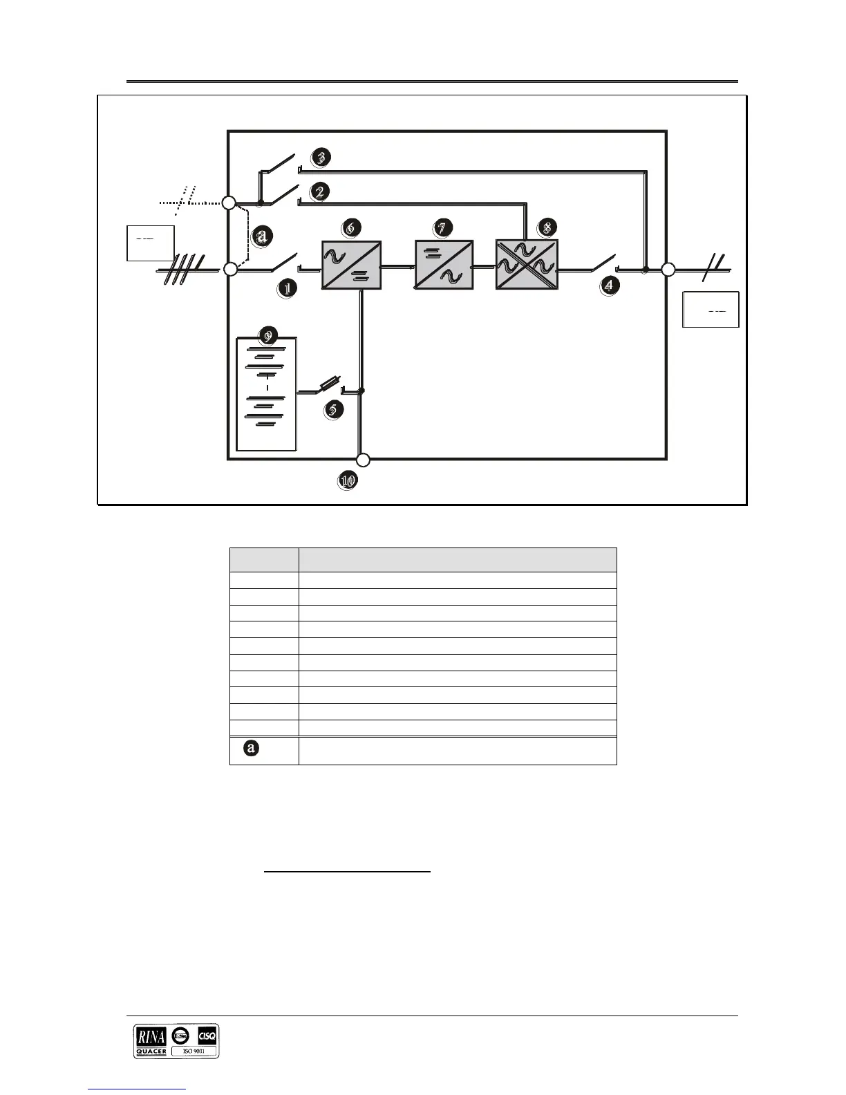
Figure 1-2 Hinet’s “Common Bypass” configuration
LEGENDA
?
INPUT MAINS SWITCH
?
RESERVE LINE SWITCH (Bypass)
?
MAINTENANCE BYPASS SWITCH
?
UPS OUTPUT SWITCH
?
BATTERY FUSES SWITCH
?
STEP-UP CONVERTER
?
INVERTER
?
AUTOMATIC BYPASS
?
BATTERY
??
EXTERNAL BATTERY PLUG
These links must be removed for split bypass
1.2.2 UPS Power Configuration
Figure 1-2 illustrates the Hinet UPS in what is known as the “Common Bypass” configuration. In the “Split Bypass”
configuration the static bypass line is connected by a separate power switch to a dedicated `bypass' power source that
also feeds the maintenance bypass line. Where a separate power source is not available the Reserve and Converter input
supply connections would be linked together.
With the exception of the maintenance bypass switch (3), all the isolators shown must be closed during normal UPS
operation.
1.2.3 Battery fuses switch
The battery is connected to the d.c. bus through a battery fuses switch (5) fitted inside the UPS cabinet.




 To Next Page